Q series Sliding Door Motor
Precautions
1. The sliding door motor is the door drive, not the limit of the door. If the door body is not equipped with a motor, the door is not allowed to derail at any position when it is manually pushed and pulled;
2. This product must be installed by professional personnel, the product is not covered by warranty if it is operated by non-professional personnel;
3. The installer must install in strict accordance with the product manual, if not, the product is not covered by the warranty;
4. It is strictly forbidden for children to operate this product without guardianship;
5. In case of use problems, please contact the dealer in time.If the above requirements are not followed when installing this product, the company will not be responsible for any problems.
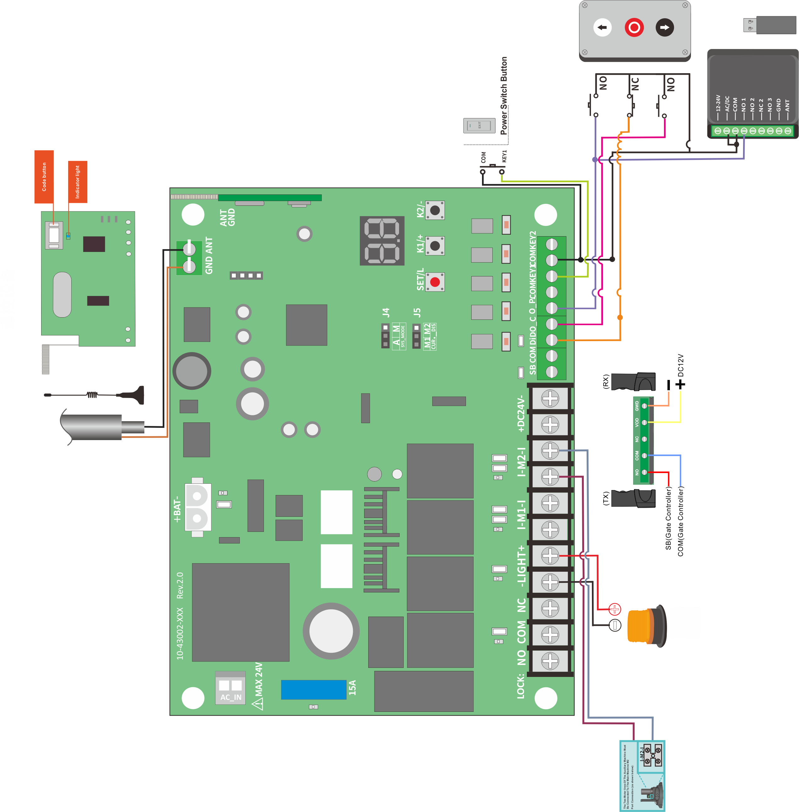
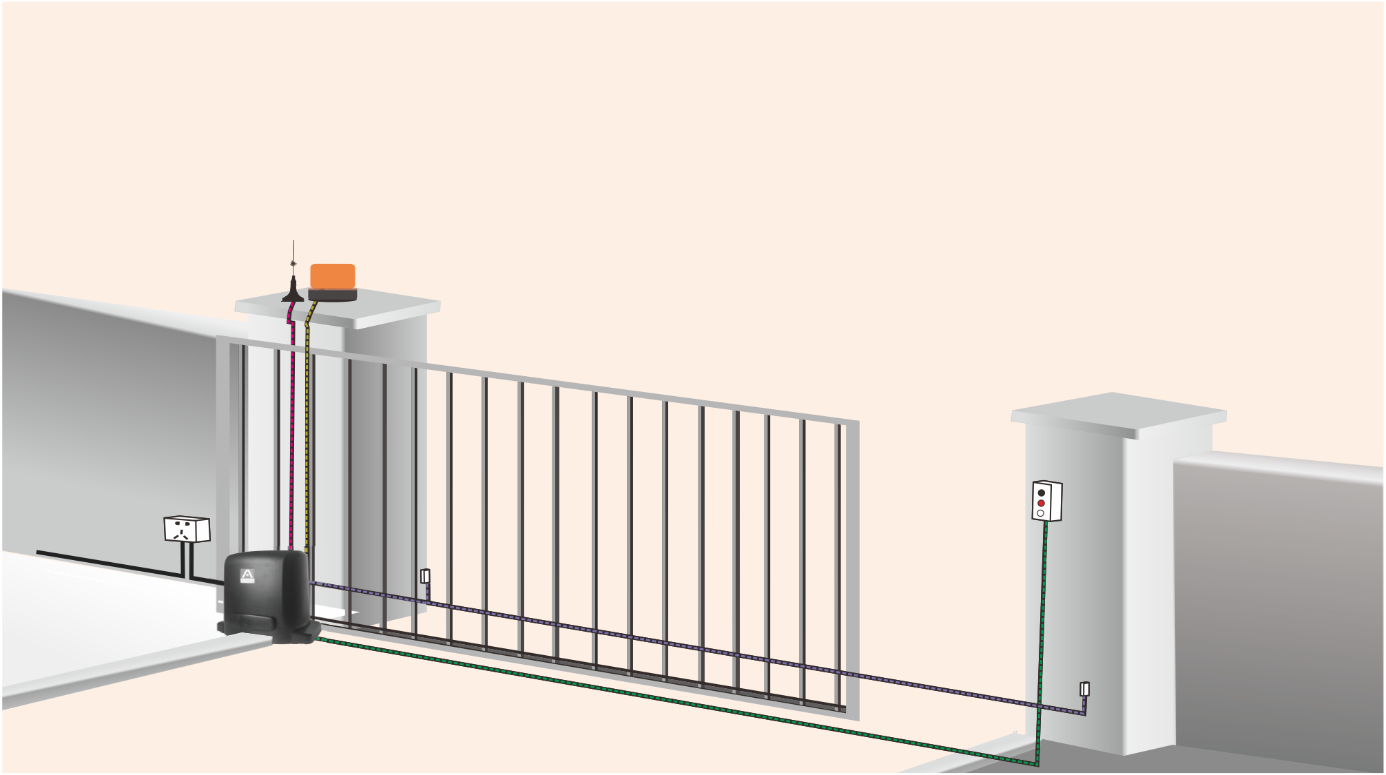
A.Wiring Diagram/Wire
| Must have | 220V AC |  |
2 x AWG15, > 1.5mm² | |
| Optional |  |
Infrared | 6 x AWG20, > 0.50mm² | |
| On/off/off |  |
4 x AWG20, > 0.50mm² | ||
| Alarm light |  |
2 x AWG18, > 0.80mm² | ||
| Antenna | 1 x coaxial |
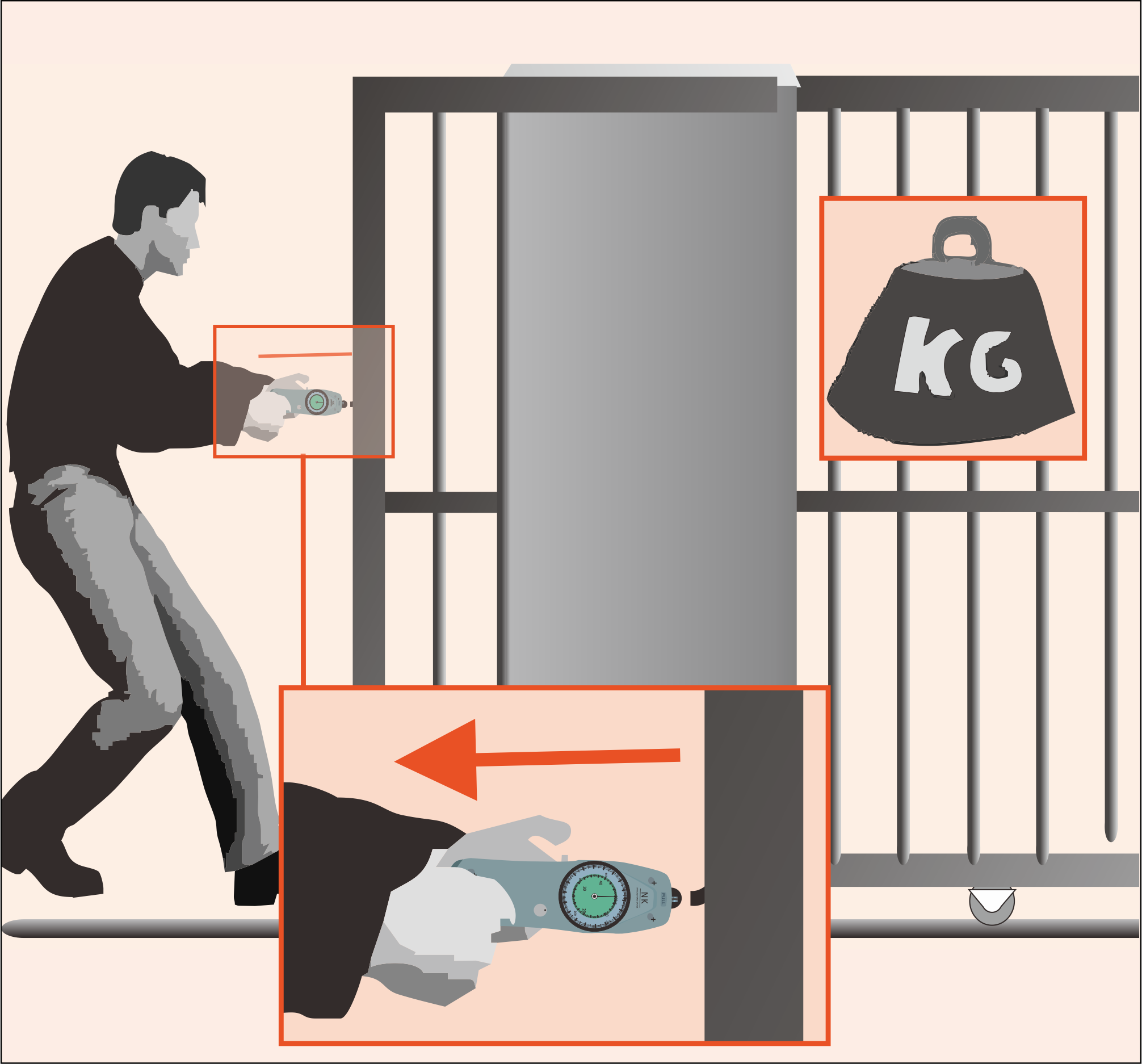
B.Choose The Right Motor Model For The Door
| Motor model | Maximum door weight | Maximum pulling force (when starting) |
Maximum pulling force (when running) |
| Q3 | 300 kg | 25 kg force | 15 kg force |
| Q5 | 500 kg | 30 kg force | 17 kg force |
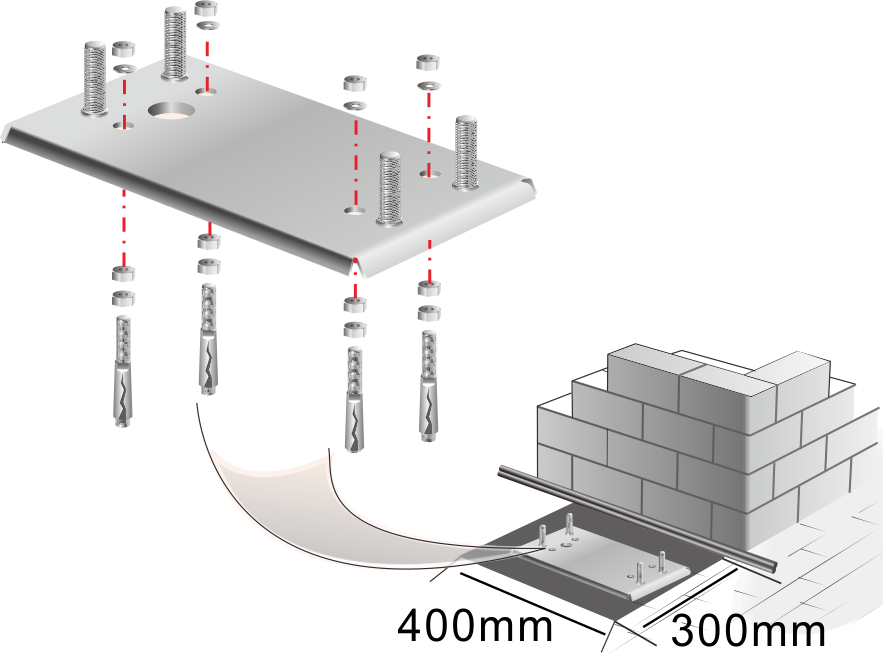
C.Install The Motor
1.Determine the motor installation Location
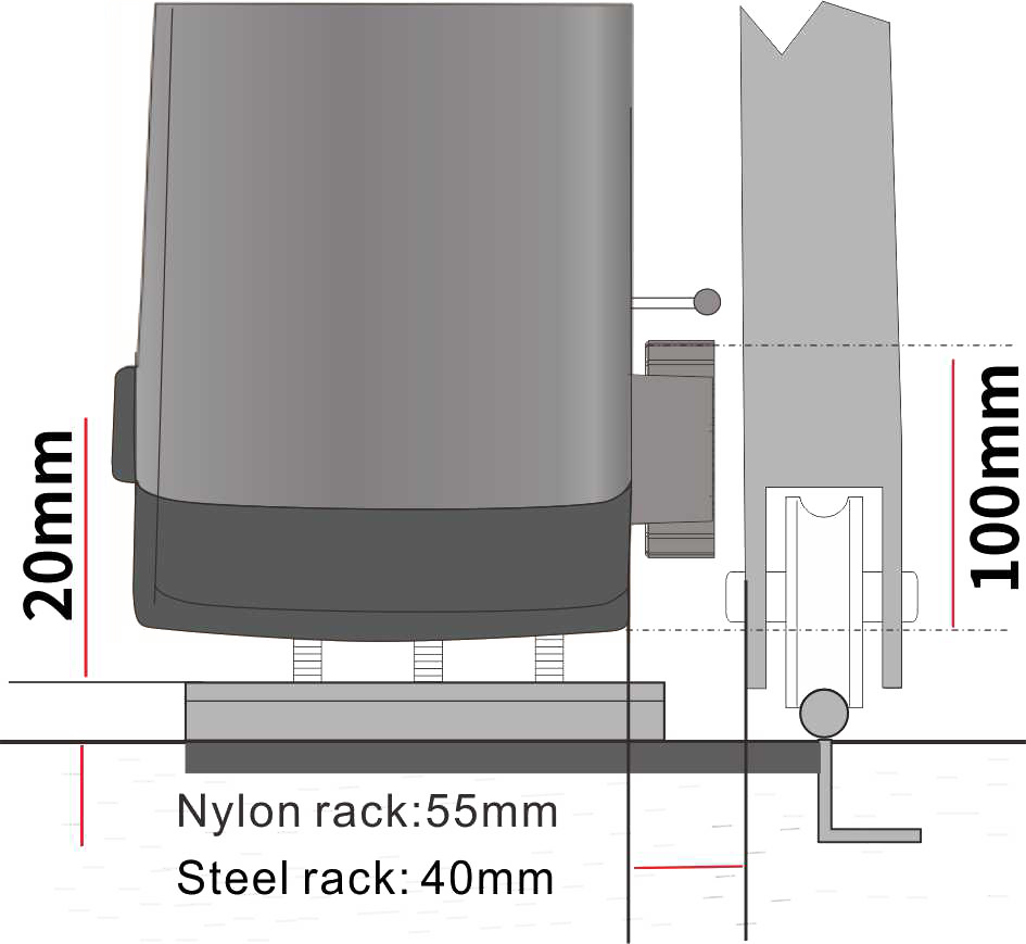
Floor height:20mm
Motor bottom to gear Height above:100mm
Distance between motor and door
Steel rack: 40mm
Nylon rack:55mm
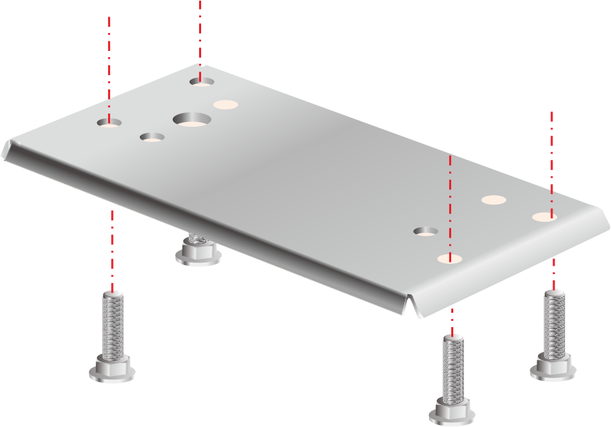
2.Install the motor fixing screw
3.Install The Bottom Plate
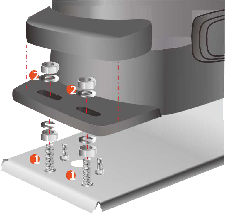
4.Fixed motor
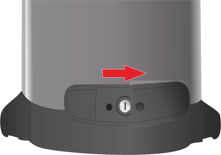
D.Manual/Electric Mode-Clutch
Manual mode: When needed (such as power outage/debugging/installation), you can manually push and pull the door.
Electric mode: By pressing the remote control/external device, the door will automatically open/close the door without manual sliding.
1.Open The Lock Cover
Slide the lock cover in the direction of the arrow to open it.
2.Insert The Key
Insert the key and turn 90° clockwise to unlock.

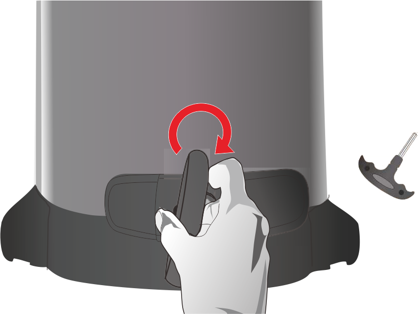
3.Manual Mode
Insert the T-shaped hexagon socket handle and turn it 90° clockwise until you hear a click, which is the manual mode, you can manually push and pull the door.
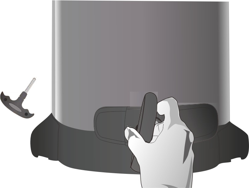
4.Electric Mode
Insert the T-shaped hexagon socket handle and turn it 90° counterclockwise, which is the electric mode.
E.Install Rack And Limit
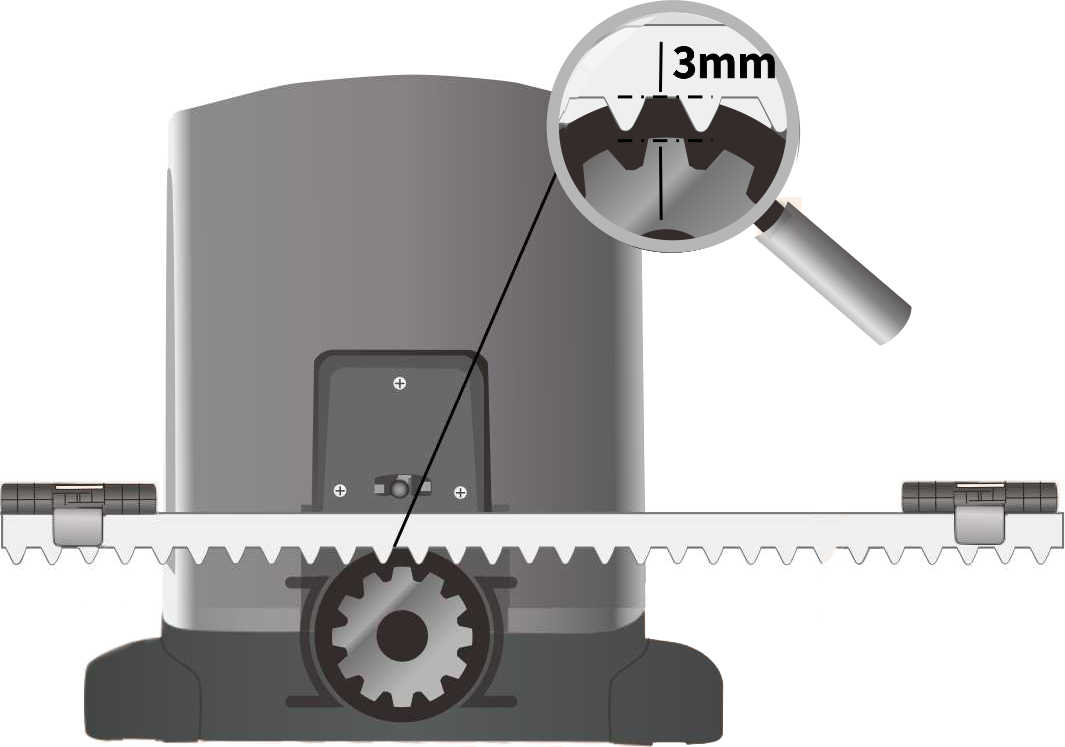
1.Install the rack
The distance between the rack installation height and the gear is 3mm.
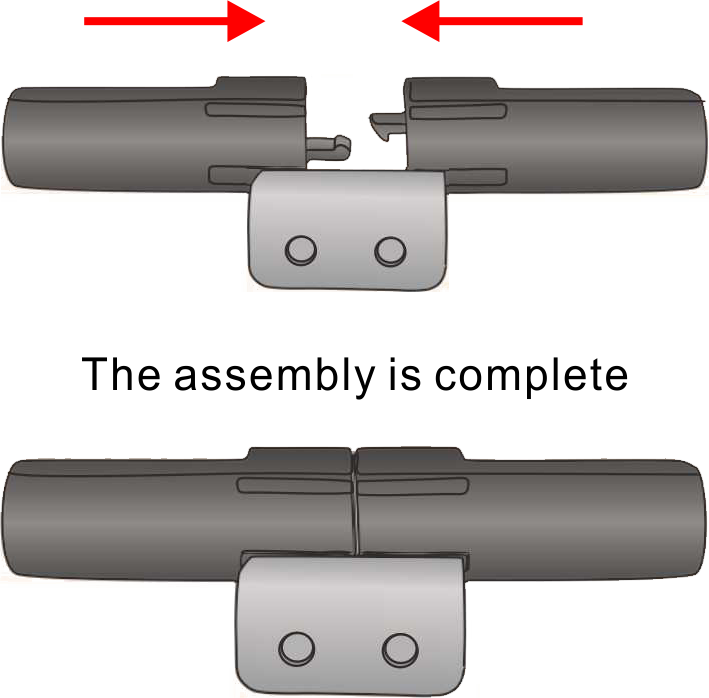
2.Assembly Limit
Assemble the limit according to the figure below.
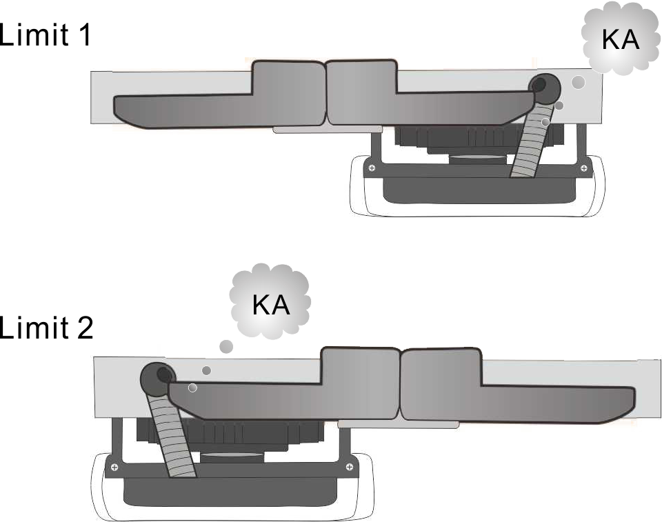
3 Determine The Limit Installation Position
Door opening limit: 1) Manually open the door to the door opening position, 2) Thickly insert the limit block on the rack, 3) Move the limit block toward the spring until you hear a “KA” sound, 4) Put the limit The block is installed in this position.
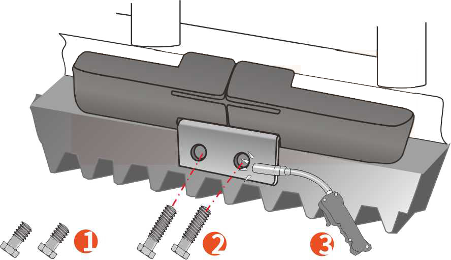
4 Fixed Limit
Thick rack (more than 10mm): fixed with short screws
Thin rack (less than 10mm): fixed with long screws
The iron rack can be fixed as above or welded with an electric welding machine
F1.Starter-Automatic Mode
A.Introduction To Automatic Mode
Auto mode is the factory standard mode
In the process of travel learning, the control system will learn the travel/time/force required to run between two mechanical limits, and automatically set all the parameters: running time/speed/sensitivity and slow stop distance.
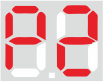
In the itinerary learning state, the display will flash, and the factory setting of the control system is in the state of learning the itinerary, and the display on the power-on display indicates that the control system has not yet learned the itinerary.
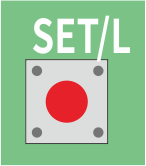
If the control system has already been used, you need to re-learn:(1)Close the door; (2)Cut off the control system power (3) Press and hold the red button Until the screen flashes
In automatic mode, the control system will automatically update the running time/speed/sensitivity and slow stop distance of the motor according to changes in the operating environment.
Standby state. Automatic trip learning has been completed, the control system is waiting for the user’s next instruction.
B.Learning Schedule
1. Install the motor in accordance with the installation limit, and then connect the power cord.
2. Manually put the door to the closed position and turn the motor into electric mode (please refer to)
3. Confirm whether the motor is in the learning state, the screen displays. If there is no screen, first enter the learning mode by re-learning according to the above steps.
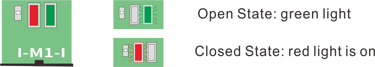
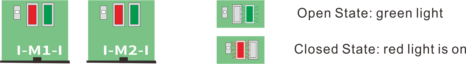
4. Press the K2/- button, the motor slowly opens the door until the “door open” position. During the door opening process, confirm that the direction indicator is green when the door is opened. If the direction indicator is not green, it is red. , Please reverse the position of the two wires on the M1 port on the circuit board (the direction indicator green represents the door opening direction, and the red represents the door closing direction). It disappears and the learning is complete.
5. After the study is completed, no other adjustments are needed, and the door opener can be used normally.
C.Additional Function Debugging
Although not necessary, the following functions can be adjusted as needed
Press the red SET/L SET/L button once to enter the function menu.Press the red SET/L button again, the screen scrolls through the different functions until the desired function, press the K1/+ K1/+ or K2/- K2/- button to display the current value, use the K1/+ or K2/- button Adjust the parameters, press the red SET/L button to confirm
| Features | Description | Numerical Value |
 |
Single door or double door option |
|
 |
Used in door opening mode. The auxiliary machine closes the door first, and the main unit delays closing the door after the set time. |
|
 |
Automatic door closing time setting, when the door reaches the door opening position, the control system will automatically close the door after the set time. At the set time, if an object passes infrared, the timer will re-time. When using this function, Safety infrared must be installed. | Turn off this feature
|
 |
The time when the warning light is pre-warned. When the warning light flashes in advance, the motor will start running; only after the door is completely closed, the warning light will go out. To use this function, you need to install the warning light (optional product). |
|
F2.Start Motor-Expert Mode
A.Expert mode Introduction
We strongly recommend that the automatic mode cannot be used only because of certain technical reasons, such as strict installation conditions and environments. Only the expert mode is required, and only professionals can set this function.
B.Startup Steps
In expert mode, the factory default normal speed running time is 6 seconds. This value is suitable for most use cases. If the door body quickly encounters rebound or stops during operation, this time needs to be reduced. Flexible running time is too long , This time needs to be increased. The flexible stop time is generally set to 3 seconds less than the total time from the door closing limit to the door opening limit.
C.Additional Function Debugging
Press the red SET/L SET/L button once to enter the function menu.
Press the red SET/L button again, the screen scrolls through the different functions until the desired function, press the K1/+ K1/+ or K2/- K2/- button to display the current value, use the K1/+ or K2/- button Adjust the parameters, press the red SET/L button to confirm
|
Same as auto mode | |
|
Same as auto mode | |
|
Same as auto mode | |
|
Same as auto mode | |
 |
Normal speed running time (seconds)-The host machine runs at normal speed during the time set here. For the remaining stroke, the host machine runs at slow speed until it reaches the mechanical limit. Normal speed running time (seconds) The slow running time of the host machine At least 3 seconds, if less than 3 seconds, you must reduce this value. | Normal speed running time (seconds) |
 |
Normal speed running time (seconds)-auxiliary machine
The description is the same as P5 |
Normal speed running time (seconds) |
 |
Sensitivity (at normal speed)
When the door is running at normal speed, it encounters obstacles or severe operating The door will reverse (in the closing direction), or stop (in the opening direction). The adjustment of this value,The door must be able to run smoothly and fully meet the safety requirements. |
Most sensitive
|
 |
Sensitivity (at slow speed)
When the door is running at a slow speed, it encounters obstacles or severe operating conditions. For safety reasons, the door will stop. The adjustment of this value must make the door run smoothly, rather than stop prematurely, and be able to Reach the pre-mechanical limit reliably. |
|
 |
speed
Use this function to choose three different running speeds |
75% of standard speed
50% of standard speed |
G1.Power Cable
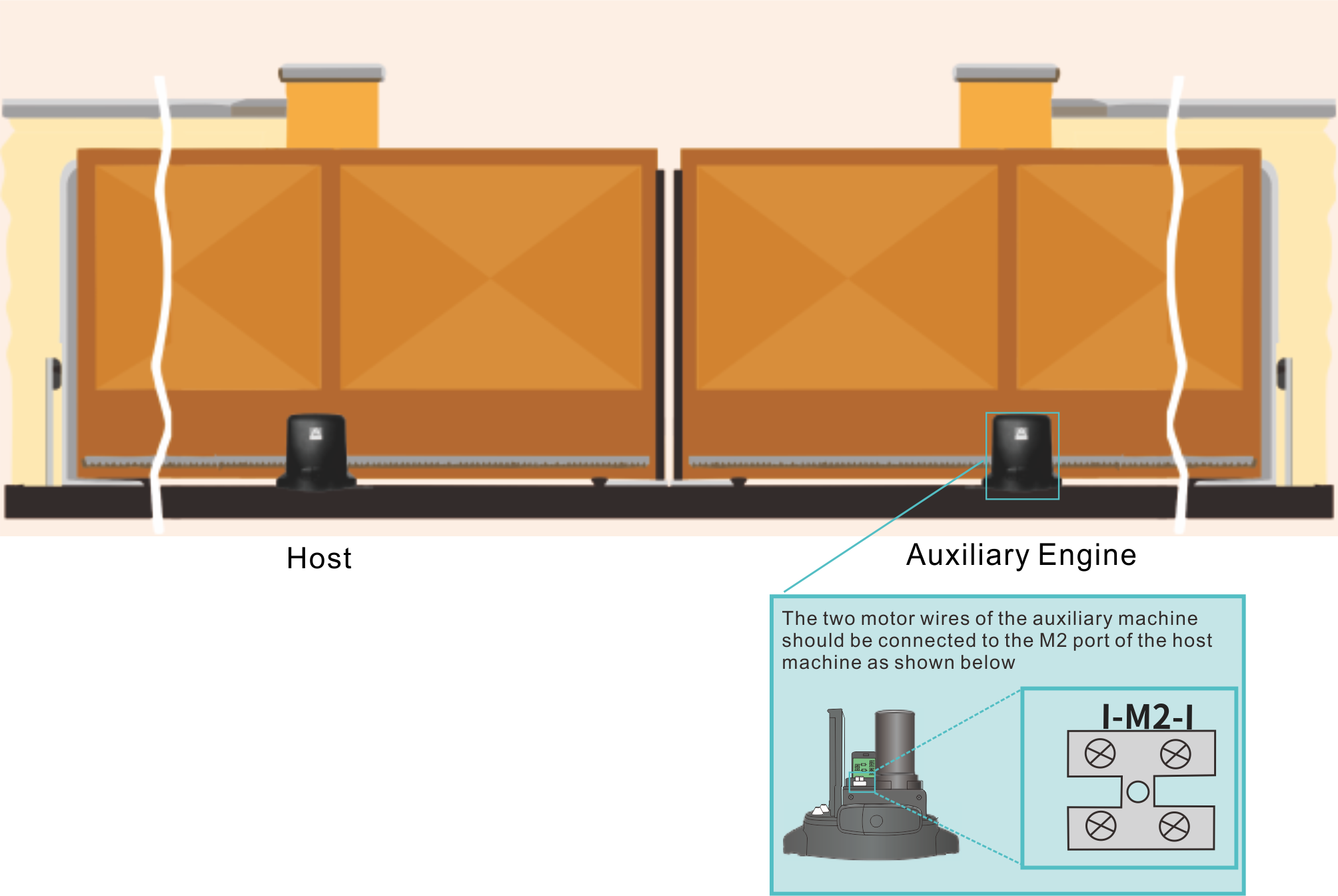
The auxiliary machine does not need to be connected to the 220V power cord. Please connect the two motor wires of the auxiliary machine to the M2 port of the main board.

Display/Button
 |
Display |
 |
Door closed state: After power on, long press until the screen flashes to re-enter the trip learning state (automatic mode)
Standby state: short press to enter the function menu; Function: short press to confirm the value. Function menu: short press to select function; |
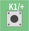 |
Standby state: short press on/off/off (host);
Function menu: Short press to enter the function; Function: Short press to increase the value. |
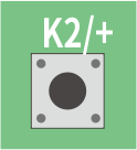 |
Standby state: short press on/stop/off (main unit, auxiliary unit)
Function menu: short press to enter the function; Function: Short press to decrease the value. |
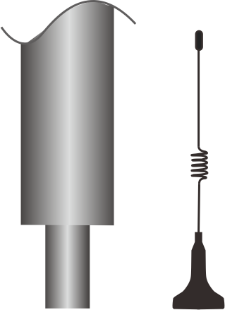
Antenna
A dedicated antenna can strengthen the receiving distance.
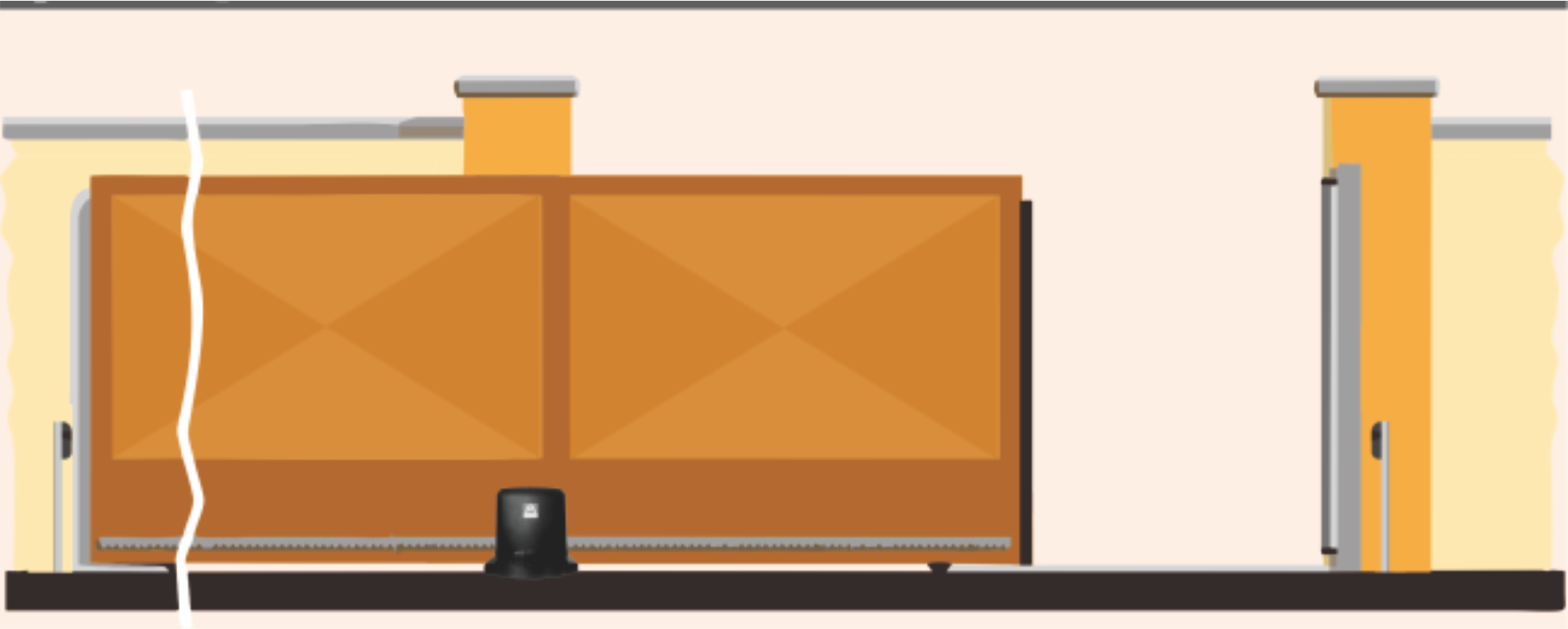
G2.Start The Motor
Single Door
Follow the F1b learning itinerary. During the learning itinerary, make sure that the M1 direction indicator is green when the door is opened and red when the door is closed. If not, you need to reverse the position of the two wires on the M1 port on the circuit board. Then follow F1b again Learning itinerary.
If the direction indicator of M1 is opposite, you need to swap the two wires of M1.
Double Door
1. To open the door, there is a main machine and an auxiliary machine. The two motor wires of the auxiliary machine should be connected to the M2 port of the main board as shown above.
2. In the menu, set P1 to 02-door mode, refer to F1c
3. Follow the F1b learning itinerary. During the learning itinerary, the M1 and M2 direction indicators are green when the door is opened and red when the door is closed. If the M1 or M2 direction indicators are not green when the door is opened and not red when the door is closed, then Need to reverse the position of the two wires on the M1 or M2 port on the circuit board. Then follow F1b to learn the itinerary again.turn off.
If the direction indicator of M1 is opposite, you need to swap the two wires of M1.
If the direction indicator of M2 is opposite, you need to swap the two wires of M1.
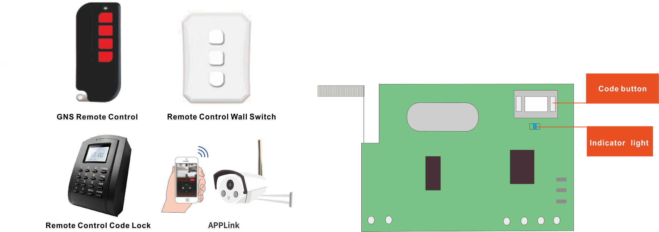
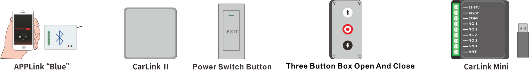
G3.Remote Control Device
Cycle “on/off/off”
Code Remote Control Equipment
Press the pairing code button twice, the blue indicator light flashes twice; long press the desired remote control device button/enter the password, the blue indicator light flashes quickly and goes out; the code matching is completed.
Pedestrian Mode Code Matching For The Open Door (main unit moving, auxiliary unit not moving)
Press the code matching button once, the blue indicator flashes once; long press the desired remote control device button/enter the password, the blue indicator flashes quickly and then goes out; the code matching is completed.
Delete All Remote Controls
Press and hold the code button for 8 seconds, the blue indicator light flashes quickly and goes out; the deletion is complete.
Specify “Open”/Specify “Stop”/Specify “Close”
A single door should have the effect of “open/stop/close” cycle,
Connect the signal line of the external device to the COM/KEY1 port.
The opposite door is connected to the COM/KEY2 port.
Door-To-Door Security Equipment
 Door-in-door device indicator Door-in-door device indicator |
Indicator light | Light does not shine |
| No door in door equipment | Normal | Not normal, DiD and COM are not shorted |
| There is a door installation device, the small door is closed | Normal | Normal Door in the door is damaged or the installation /connection is incorrect |
| There is a door installation device, the small door is open | Normal Door in the door is damaged or the installation /connection is incorrect |
Normal |
If the door-to-door device is not installed, DiD and COM must be short-circuited. If there is a small door with a pedestrian walkway on the door, this safety device must be installed. When the small door is opened, this safety device will be disconnected, regardless of any instructions, The gate will remain stopped.
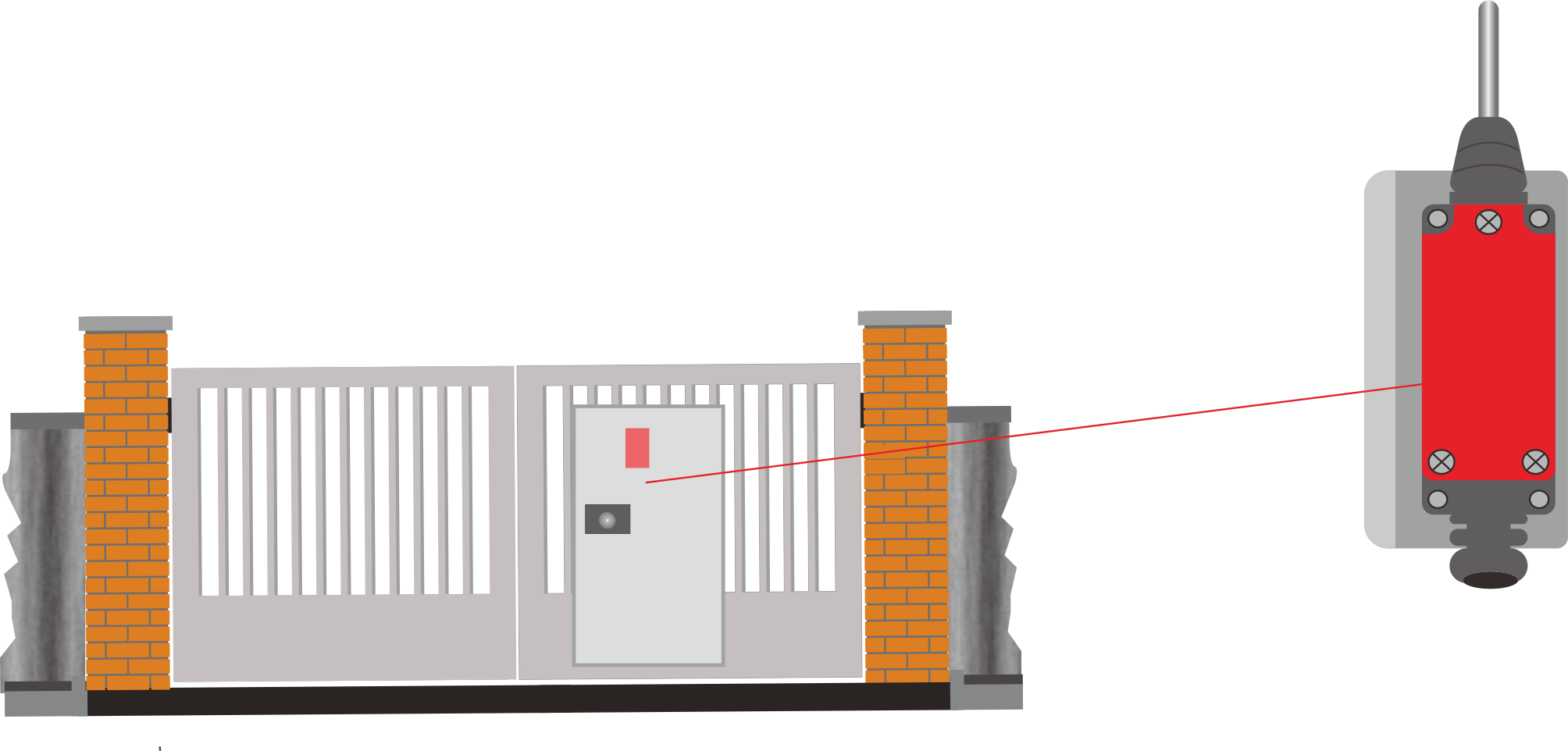
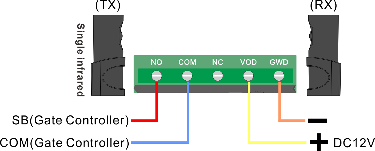
Safety Infrared (Electric Eye)
If infrared is not installed, SB and COM on the circuit board must be shorted.
 Door-in-door device indicator Door-in-door device indicator |
Indicator light | Light does not shine |
| No infrared | Normal | Not normal, DiD and COM are not shorted |
| With infrared light, no obstacles | Normal | Normal Door in the door is damaged or the installation/connection is incorrect |
| There are infrared lights and obstacles | Normal Door in the door is damaged or the installation/connection is incorrect | Normal |
Alarm light 24V DC
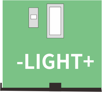
 |
Light on: The alarm light is flashing, and the door is not completely closed. |
 |
Lights are off: The alarm light is off and the door has been completely closed. |
When the door is in operation or not in the fully closed position, the alarm light will flash. When the door is in the fully closed position, the alarm light will go out.
be adjusted through P4, please check C.

Controller Diagram