Connections
| Pin | LD-100 | LD-102 | 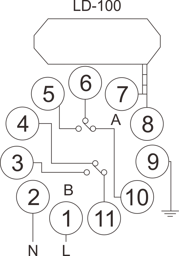 |
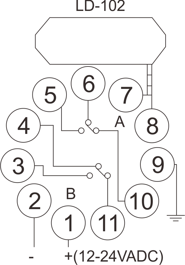 |
| 1 | 100-240V AC | 12-24VADC | ||
| 2 | 100-240V AC | 12-24VADC | ||
| 3 | Pulse B Relay N.O | |||
| 4 | Pulse B Relay COM | |||
| 5 | Presence A Relay N.O | |||
| 6 | Presence A Relay COM | |||
| 7 | Loop | |||
| 8 | Loop | |||
| 9 | Chassis Ground | |||
| 10 | Presence A Relay N.C | |||
| 11 | Pulse B Relay N.C | |||
2.Indicates And Switch
(1)Power Led: RED power LED indicates “Power ON”
♦ Detecting Led: Continuously On: Indicates vehicle detection.
♦ Blinking slowly: Indicates loop is short circuit or the number of twists after the loop is not enough.
♦ Blinking fast: Indicates loop is open circuit or too many twists after the loop.
(2) Switch 1 (Trimpot), Sensitivity Selection
♦ Sensitivity of the loop can be adjusted by the trimpot labeled “Sensitivity”. User can select 16 differentsetting by turning the trimpot with 0
being the least sensitive and “F” being the most sensitive.
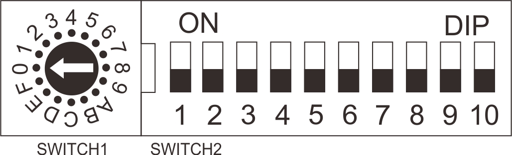
(3) Switch 2 (Dipswitch Settings)
♦ DIP 1 & DIP 2 Setting Special Functions
| DIP NO. | DIP MODE | Function |
| DIP 1 | ON | Output has 2 seconds delay. (No relay output if the vehicle speed is over 8km/h) |
| DIP 2 | ON | Increase sensitivity to avoid unwilling relay off for leaving vehicle especially for trailer. |
DIP 3 & DIP 4 Setting Relay B Output
| DIP NO. | DIP 3 | DIP 4 | Relay B Output | Loop Coils Status |
| DIP MODE | OFF | OFF | When vehicle is moving out, output for relay B is 200m/s | Relay B Output Type |
| ON | OFF | When the vehicle has left, output for relay B is 600m/s | Relay B Output Type |
|
| OFF | ON | Relay B will be present output. No reaction on Dip switches 3. | Relay B Output Type | |
| ON | ON | Can be used to test the Loop. If the loop is faulty, Relay B will be on and it will switch off once the fault is fixed. | ||
DIP 5 Setting Automatic Reset
| DIP NO. | DIP 5 | Present Mode |
| DIP MODE | ON | Vehicle can be permanently present (no auto-reset , unless vehicle has left or manual reset) |
| OFF | Normal mode (automatic reset after 30 minutes present of vehicle, used to solve the mistake operation. If it is recommended). |
DIP 6 & DIP 7 & DIP 8 Setting Relay A Delay
| DIP NO. | DIP 6 | DIP 7 | DIP 8 | Delay | A Output |
| DIP MODE | OFF | OFF | OFF | 0 sec | Output |
| ON | OFF | OFF | 2 sec | Output |
|
| OFF | ON | OFF | 5 sec | Output |
|
| ON | ON | OFF | 8 sec | Output |
|
| OFF | OFF | ON | 10 sec | Output |
|
| ON | OFF | ON | 15 sec | Output |
|
| OFF | ON | ON | 20 sec | Output |
|
| ON | ON | ON | 30 sec | Output |
DIP 9 & DIP 10 Setting Frequency (40 K to 100 KHz). Used to avoid the interference
| DIP NO. | DIP 9 | DIP 10 | Frequency |
| DIP MODE | OFF | OFF | High |
| ON | OFF | Medium-High |
| DIP NO. | DIP 9 | DIP 10 | Frequency |
| DIP MODE | OFF | ON | Medium-Low |
| ON | ON | Low |
∗ In the application, where two or more loop detectors and sensing loops have been installed, set onedetector to high frequency and the
other set to low frequency to minimize the effects of cross-talk betweenthe two systems(The sensing loops and detectors should be
positioned at least 2m apart).
∗ Reset Button:Please note: The LD-100 must be reset every time a setting change is made to the Dip switches.
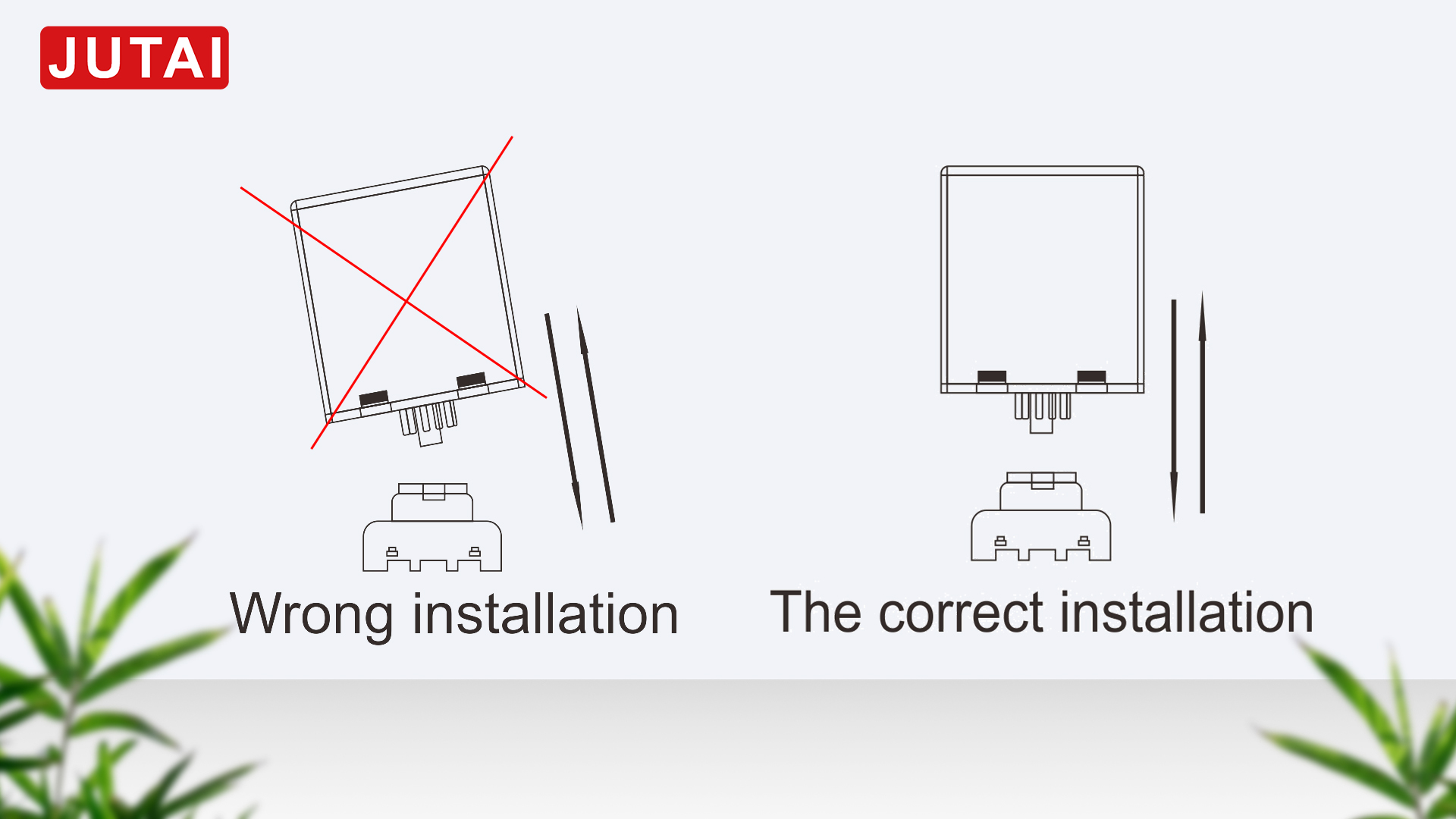
3.Detector Position And Installation
-Install the detector in a weatherproof housing.
-The detector should be as close to the sensing loop as possible.
-The detector should always be installed away from strong magnetic fields.
-Avoid running high voltage wires near the loop detectors.
-Do not install the detector on vibrating objects.
-When the control box is installed within 10 metres of the loop, normal wires can be used to connect the
control box to the loop. More than 10 metres requires the use of a 2 core shielded cable. Do not exceed 30
metres distance between control box and loop.
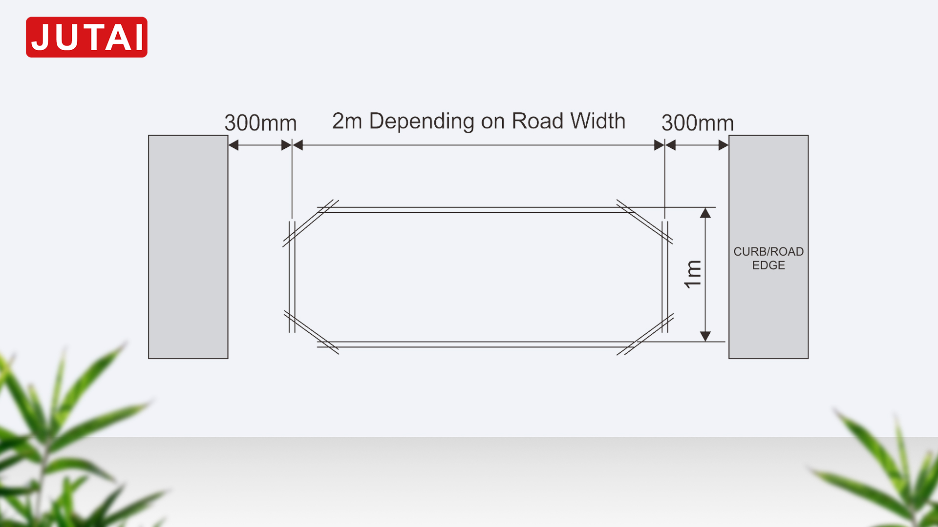
4.Loop Installation
The loops are sealed using a “quick-set” black epoxy compound or hot bitumen mastic to blend with the roadwaysurface.
| Loop perimeter | Cylinder numbers |
| 3 ~ 4 M | 6 |
| 4 ~ 6 M | 5 |
| 6 ~ 10 M | 4 |
| 10 ~ 20 M | 3 |
| 20 M~ UP | 2 |
TroubleShooting
| Symptoms | Solution | |
| If the detector is not working | Press reset | |
| If red led indicator is not fully lit | Check for power supply | |
| If green led indicator | Blinks slowly | It maybe because the loop is short circuit or the no: of turns is not enough. |
| Blinks faster | It maybe because the loop is open or the no: of turns is too many. | |
| If no: of turns is not enough | Lower the frequency (if the frequency is still too high, you must add more turns). | |
| If no: of turns is too many | Higher the frequency (if the frequency is still too low, you must remove some turns). | |