Packing List :
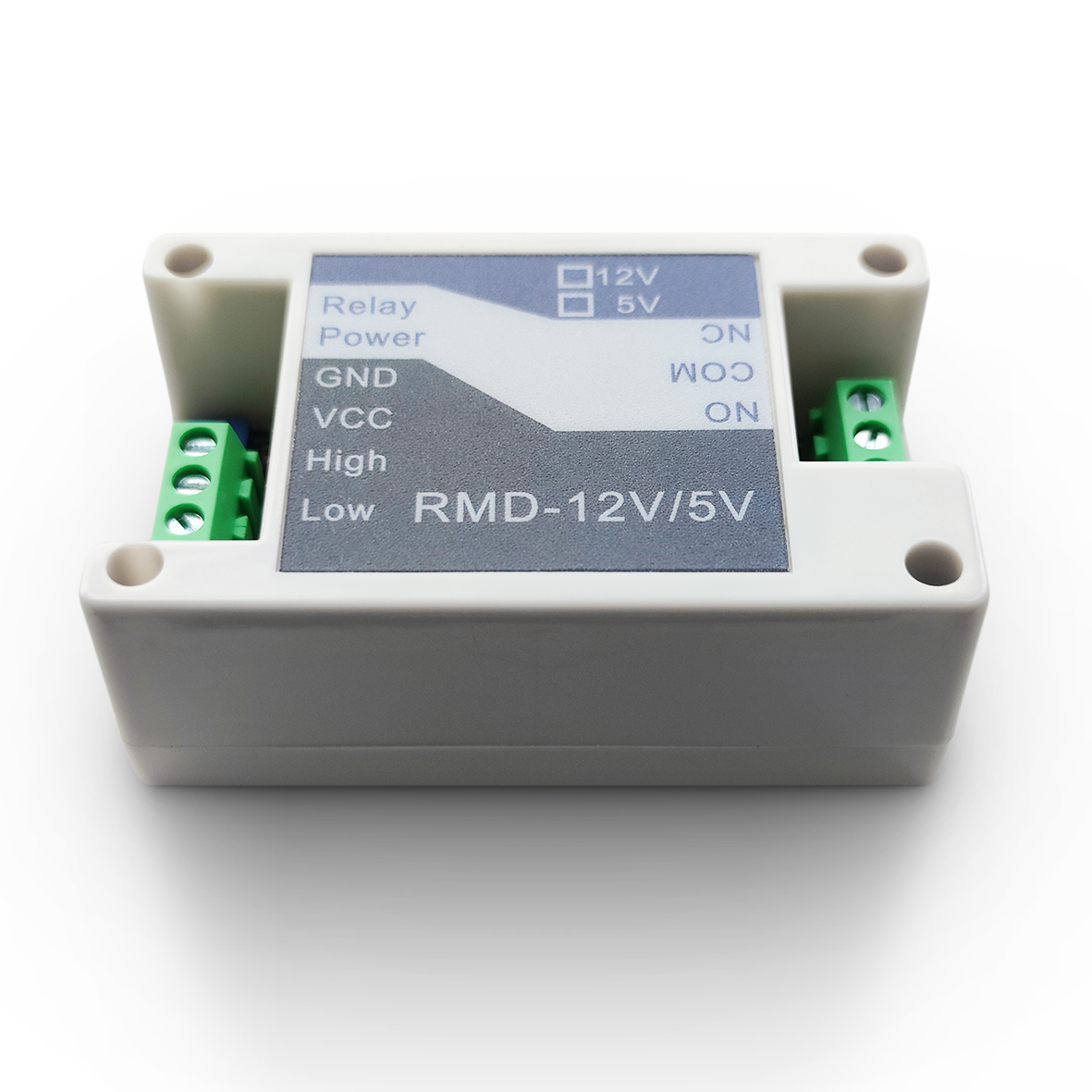
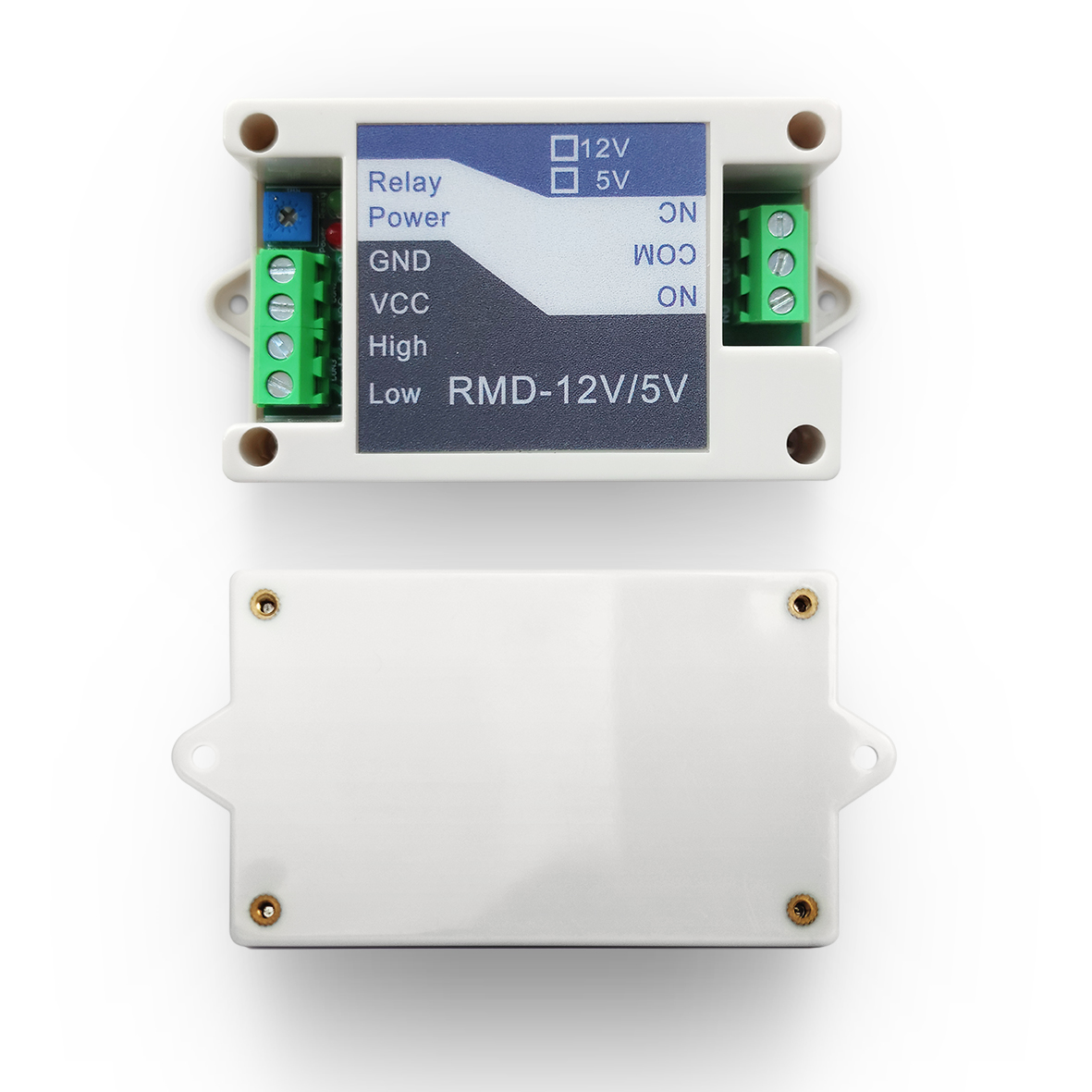
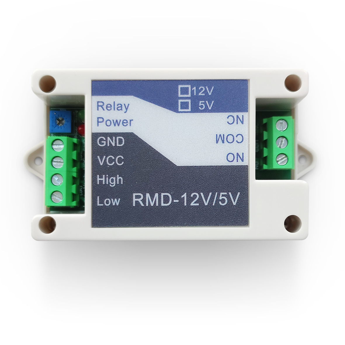
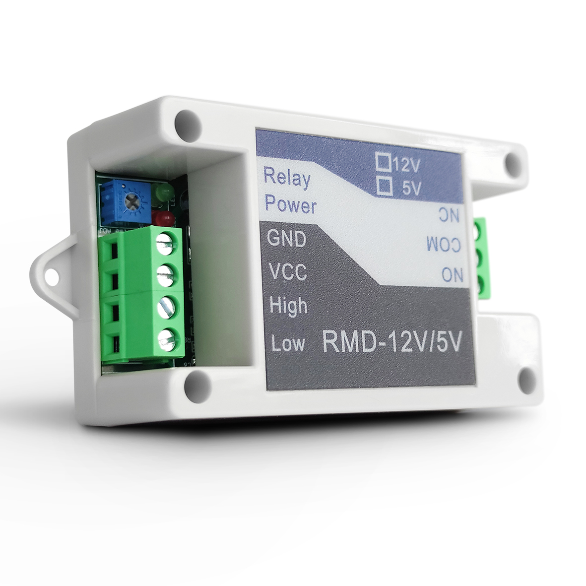
1.RMD-12Relay Convertor 1pcs
2.Operation Manual 1set
3.M3*6 2pcs
Installation : (Unit : mm)
1.First Step, Drill the fixing holes on the fixing panel according to the install
hole size on cover surface ;(Diameter:2.5MM)
2. Next, use M3*6 screws to fix the module on the fixing panel;
3.Connect 12v/5v power supply ,and testing ;
4.The red light is always on, the module is in standby status, and the green
Color light is always on, module relay output signal;
Technology Parameter:
| Power Supply | 12VDC/5VDC(Depends on the selected module) |
| 12V Static Power Consumption | 5.5mA |
| 12v Max Power Consumption | 42mA |
| Relay load | 5A 30VDC(DC) 10A 250VAC(AC) |
| Time Delay Range1 | 0.13S-1.3S |
| Time Delay Range2 | 1.5S-14.5S |
| Time Delay Range3 | 0.5S-5.2S |
| Time Delay Range4 | 6S-58S |
| Time Delay Range5 | 4.4S-42S |
| Time Delay Range6 | 48S-463S |
| Time Delay Range7 | 38S-340S |
| Time Delay Range8 | 389S-3700S |
Trigger Time Setting:
| Photo Shows | Function description |
 |
High Level Trigger Input |
 |
Low Level Trigger Input |
| S1 | S2 | No Short S4 | Short S4 |
| 0 | 1 | 0.13S-1.3S | 1.5S-14.5S |
| 1 | 0 | 0.5S-5.2S | 6S-58S |
| 0 | 0 | 4.4S-42S | 48S-463S |
| 1 | 1 | 38S-340S | 389S-3700S |
Port
Example
Size(mm):
Electronic Connection:
| Items | Color | Function |
| BN | Brown | Power positive |
| BK | Black | NPN Output |
| BU | Blue | Power negative |


