MR-1P 13.56Mhz Short Range Reader
Packing List:
1,Reader 1 Unit
2,User Manual 1 Pcs
3,Line 6PIN
4,Screw M3.5*21 Four Pcs
Installation: (Unit: mm)
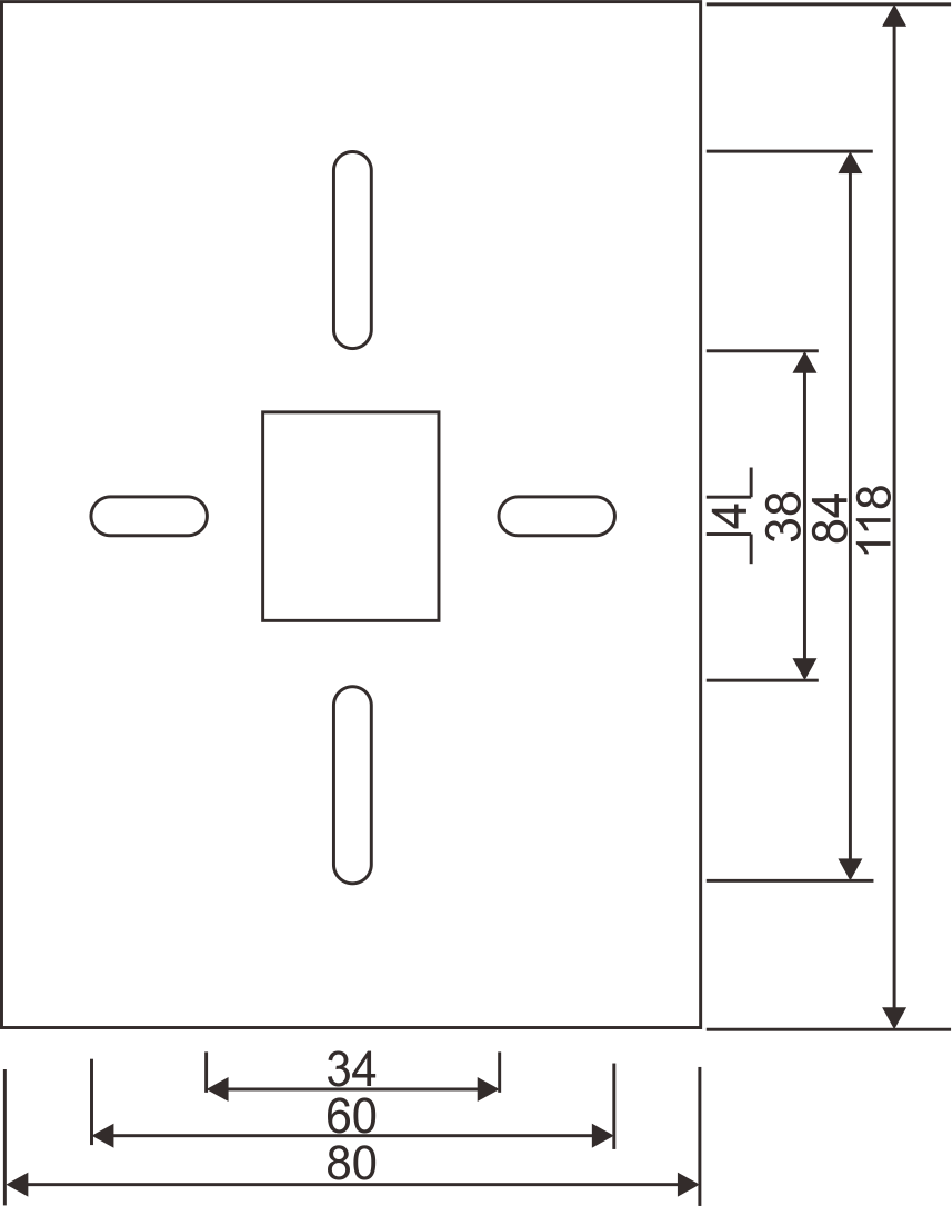
◊ Use a screwdriver and screws to fifix theback cover on the wall.
◊Connect the wire splice to the corresponding line of the reader.
◊Install MR-1P reader on the back cover and fifixed screws by screwdriver after hole is adjusted well.
◊ After power on, blue light bright
◊Pine line:Transmission signal cable and power cable do not confifigured in the same line,should be separated.
◊Power supply:MR-1P short range reader and controller should use same power supply or same negative port,or else the Wigand data communicatior will be error.
LED Indicator:
| Indicator light | Function |
| The blue light flflashes slowly | Power supply is normal, the blue light
flflashes slowly,the reader in the standby state |
| The blue light flflashes quickly | Once the card is read, and the blue light flflashes once. |
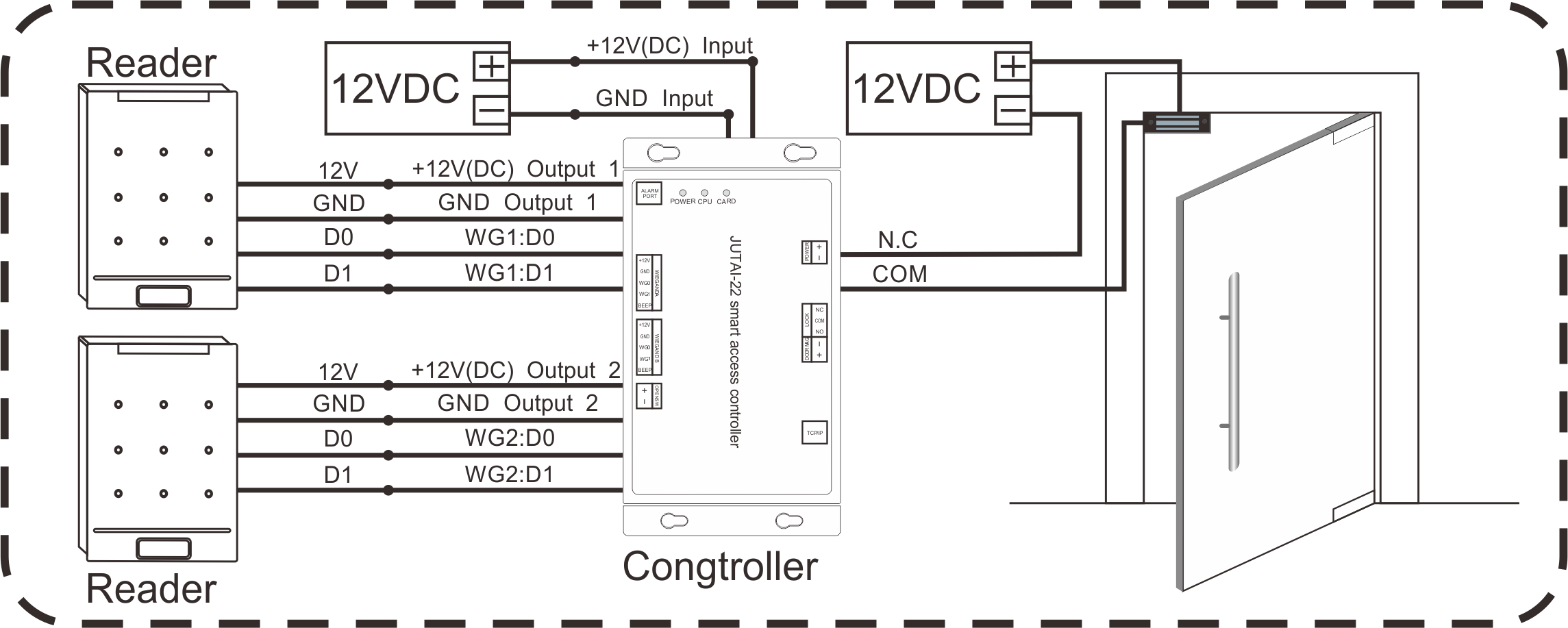
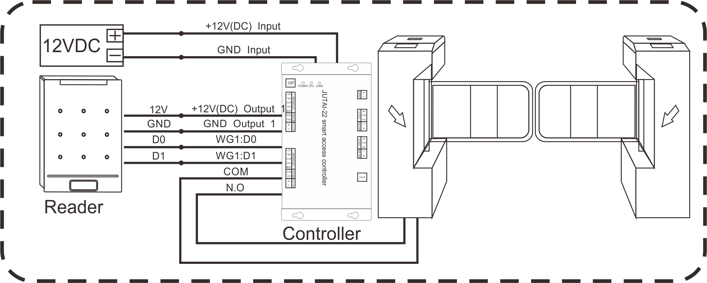
Connection Line Definition:
| NO | Color | Function | Describe |
| 1 | Red | +12V | 12V Power |
| 2 | Black | GND | |
| 3 | Green | D0 | D0 ( Wigand data 0 ) output |
| 4 | Yellow | D1 | D1 ( Wigand data 1 ) output |
| 5 | White | RS485-A | Function reservation |
| 6 | Brown | RS485-B |
A.RFID Turnstile system application
B.RFID Access control system application