1 . Main Introduction
· Main be used for highway , using life more than 5 millions times , good proteciton design for human body and vehicle.
· 35-70 degree working environment.
· Indepent patent , Mchine Accuracy less than 0.2mm , wather proof constructio.
· Without independent reduce gears , and which is main for reducing fault points.
· 32bit high-performance ARM core , 72MHZ procession capacity , for ensure user opeation and fast response.
· Support 3D Equipment Siatus detection,high speed sample frequency and reach to 10 bit sampling percision,making sure device working with fast speed ,and stable status,self-calibration when poweron,Completely avoid the remediation work caused by the difference of site installation.
· Support TCP / IP , allow customers remote controlling device though internet , The terminal work status and event formation can be obtained in real time.
· Support WEB brower , allow customers visit device base on any IE broswer , and query and edit to deviec parameter.
· Secure communication and password protection to prevent malicious network attacks.
· Multi-type motor for selection,Suitable for vehicles with high traffic flow and high safety level, such as entrance, port,airport highway toll booth, etc.
2 . Main Function
Parameter
| Model | JT-09S | JT-14S |
| Power Supply | AC230V | AC230V |
| Power Frequency | 50/60Hz | 50/60Hz |
| Motor Rated Power | 80W | 80W |
| Motor Rated Speed | 30r/min | 22r/min |
| Motor Norminal Torque | 20N·m | 20N·m |
| Arm Length | 2.5M | 3.00M |
| Running Noise | ≤60dB | ≤60dB |
| Arm Up time | 0.9s | 1.4s |
| Arm Down Time | 1.0s | 1.4s |
| Running Life | ≥5 Million | ≥5 Million |
| Tempting | -40℃~+75℃ | |
| Relative humidity | 50%~+90% | |
3 . Safe Notice
3.1 Genera
• The high-speed barrier gate has been carefully designed, manufactured and tested, and has been properly adjusted before leaving the factory. In the installation and use, if the instructions are not strictly installed, the operation may result in personal injury or damage to the equipment.
• For ensure your safe operation,and reduce accident happened,please read user manual carefully before installlation and operation according to it strictly.
• The correct installation and use of high-speed barrier and which can fully obtain the quality commitment and perfect after-sales service promised by the manufacturer.
• It is applicable to the automatic charging system of highway, car park entrance and customs clearance.
3.2 Safe Notice
• When the arm barrier up/down, No one is allowed to stand or walk under it;It is strictly prohibited to stand and put objects in the area of the rails.
• when operation, must pay attention to observe the rail ups and downs and its surrounding. In the process of railing, if there is no special circumstance, it should not stop its up and down.
• Should cut power supply if power off,up the arm by manual,and connection power supply after power on.
• Installation and wiring must be in accordance with the construction standards and electrical procedures.
• Adjust the tension spring, set the operating mode, install the infrared detection device, be sure to ask professionals to operate.
3.3 Safety Signs
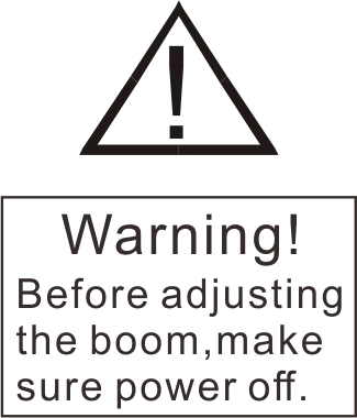
When installing the automatic boom, please note the following symbols in the manual:
 |
Warning | This symbol indicates that the operation must be carried out strictly according to requirements, otherwise it may cause serious personal injury. |
 |
Notice | This symbol indicates that operation must be performed strictly as required or the equipment may be severely damaged |
 |
ZRemind | This symbol indicate relevant and useful tips |
4.Installation
4.1 Packing list
1. high-speed barrier gate*1
2.Fitting iron*2
3.User manual*1
4.Clamp head
5.Expansion screw*4
6.key*2
7.Certificate
8.Manual button (or remote control)
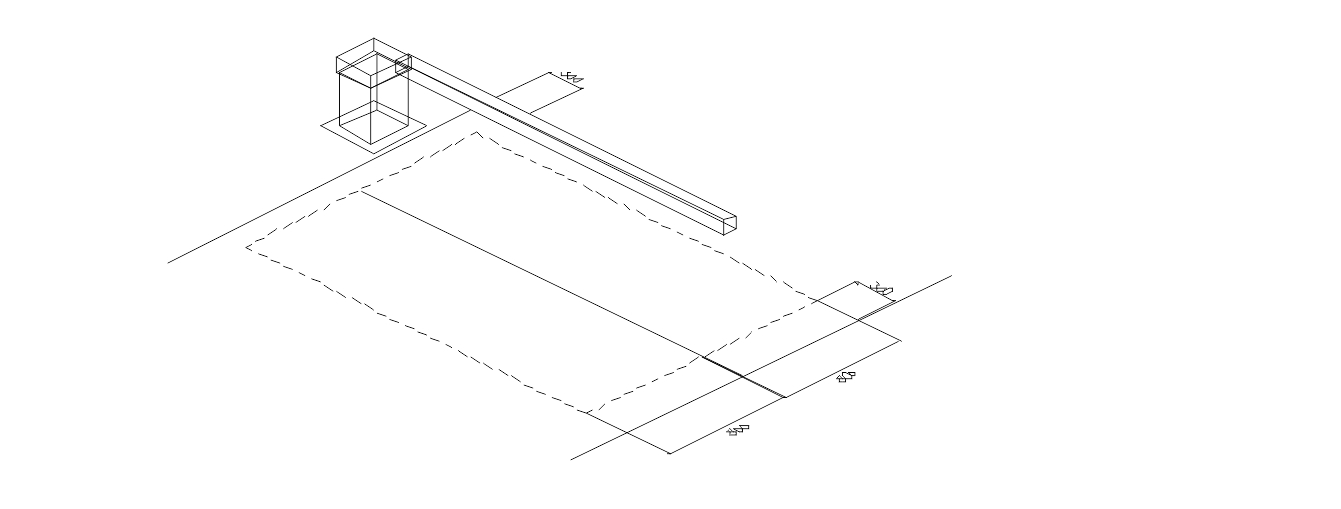
4.2 Auxiliary foundation
According to the actual situation on the scene, to determine the installation location of automatic railings (non-concrete foundation should be done concrete base). Figure 4.1 is recommended for manufacturers of automatic boom And its accessories Typical installation layout diagram.
4.3 Install the chassis
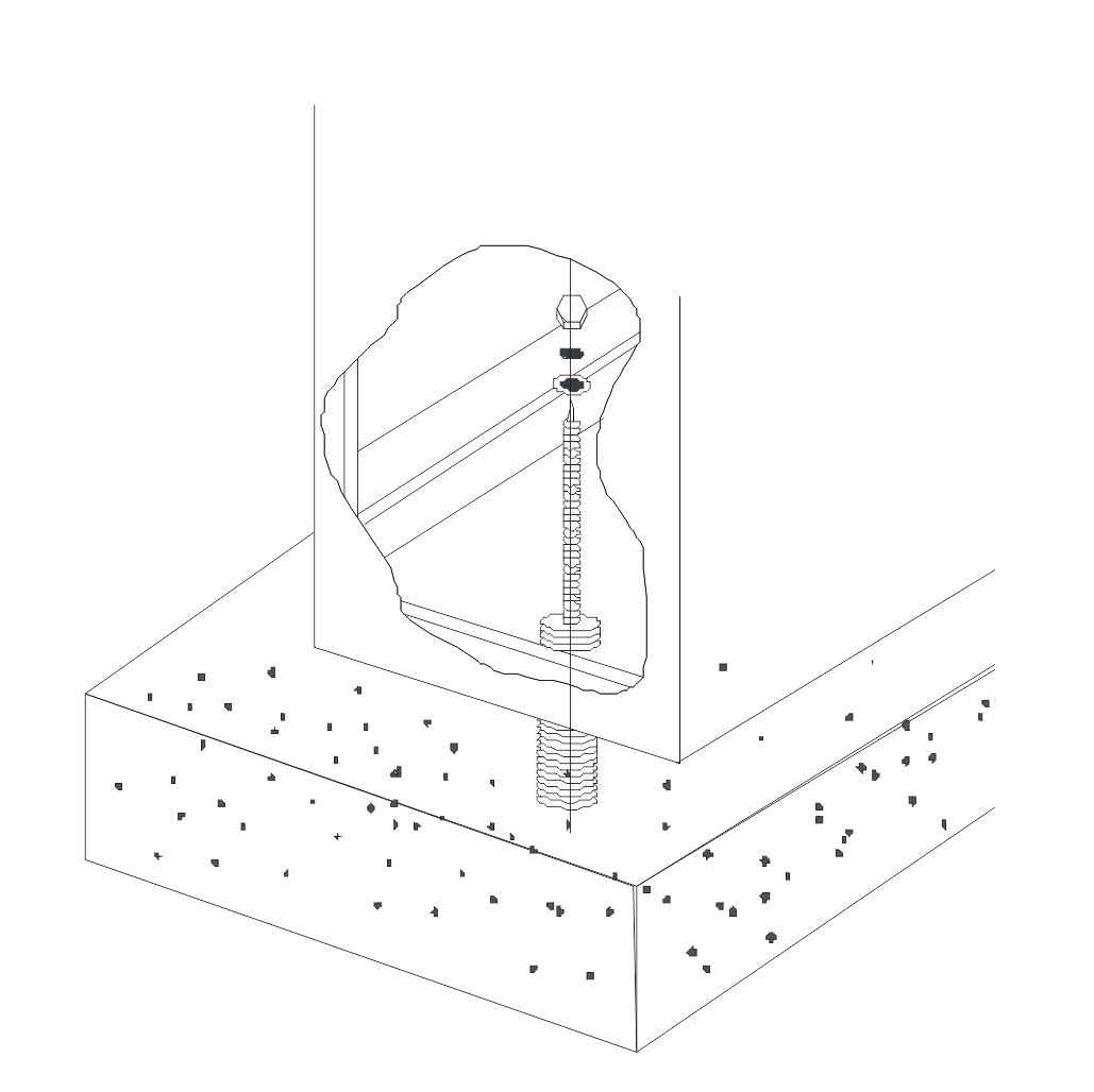
• Determine the installation position of the automatic lever and fix the anchor bolts (four) for the chassis.
• Ann
• Can be used when equipped with randomly distributed installation template drilling, and pay attention to the anti-collision mechanism and the direction of the car
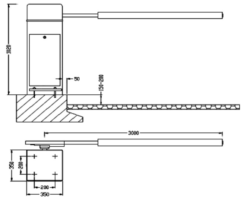
• Vehicular traffic in the same direction. The embedded size and related dimensions shown in Figure4.2
Embedded size and installation dimensions
Check the accessories, remove the platen assigned to the high-speed car body is fixed to the base. Need to adjust the orientation of high-speed gear when the car just loosen the nut, and then need to adjust the automatic lever to the proper position and angle, then the anchor bolts can be fastened.
Chassis adjustment method
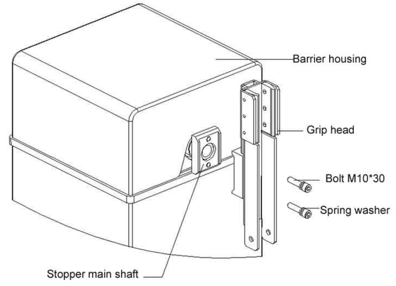
4.4 Install the boom
As shown in Figure 4.4, remove the two screws from the stopper main shaft and install the accessory (clamp head) in the groove on the extended end of the stopper main shaft. Use the removed M10 bolt to secure the grip head to the stopper spindle.
Install the boom schematic
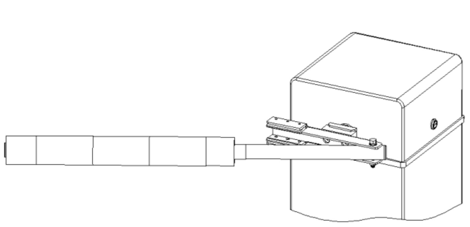
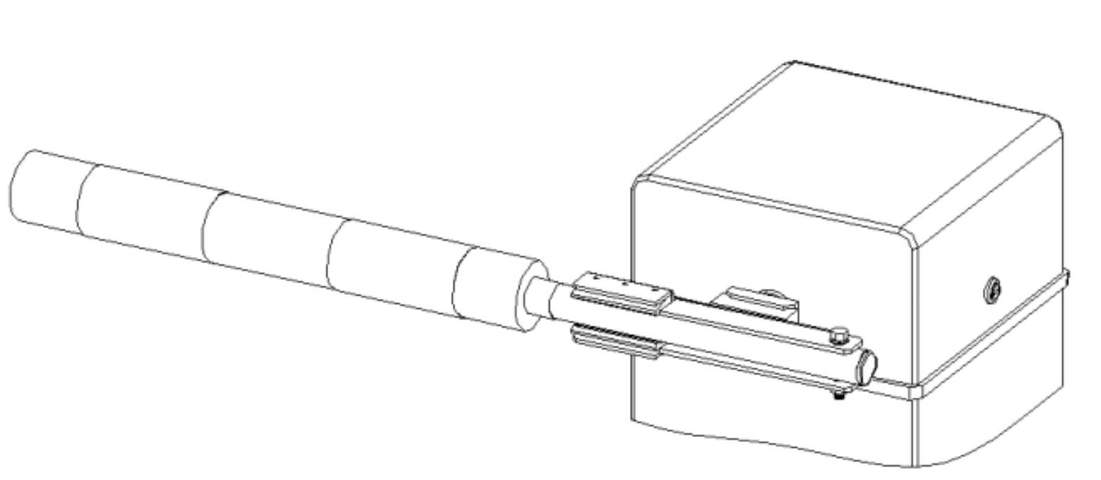
4.5 Arm Installation
Remove the railing, the tail end of the railing with a screw to wear in the clamp head, the screw as the center of rotation, forced the railing into the clamp head, as shown in Figure 4.6, tighten the railings with a wrench to prevent loose.
4.6 After installing the boom
After the installation is complete, check the railings (closing gate) is in the ideal position, if the railings are not satisfied, can be adjusted as shown below.
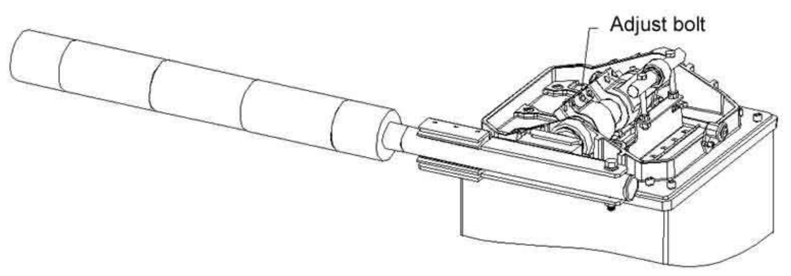
4.7 Boom adjusting
Slowly loosen the two adjusting screws (M12) shown in Figure 4.7 with a hexagon wrench and the railings are free and the railings are adjusted to their desired positions. Tighten the adjusting screws and the railings are adjusted.
5 .Controller and connection

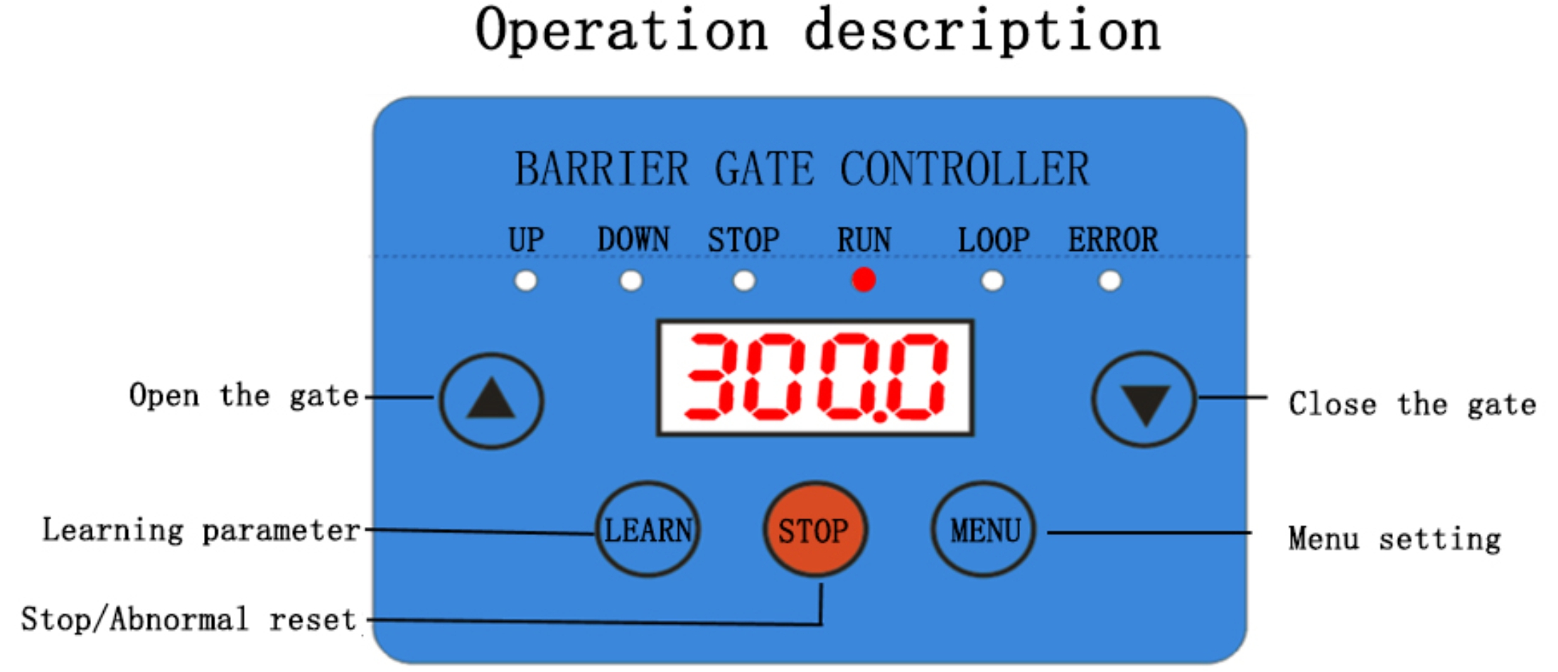
5.1 Controller definitions
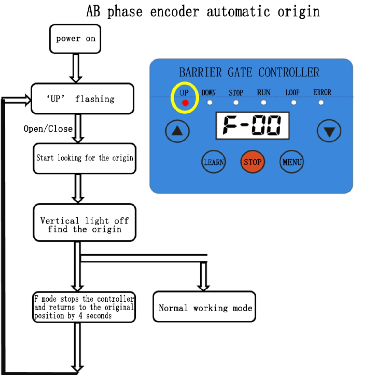
1.The controller is powered off and re-powered. Pressing “UP”or “DOWN” will automatically find the origin(Vertical Position), and the lever can work normally after successful operation.
2.The controller is constantly powered,and in the F-x mode (except F-04), press the stop button until the vertical light flashes and then release, then press any key up and down to automatically find the origin(Vertical Position).
Display Items Description
This controller main have 2 functions,one is F-xx,which mainly used as learn and monitor,second is P-xx,which main used as update application parameter,long press function button 2-3s and can switch F and P.
| Content | Description | Remark |
| F-00 | Monitor parameter code | Press Function button can switch |
| P-00 | Setting parameter code | Press UP/DOWN can switch |
| 20 | Current display value |
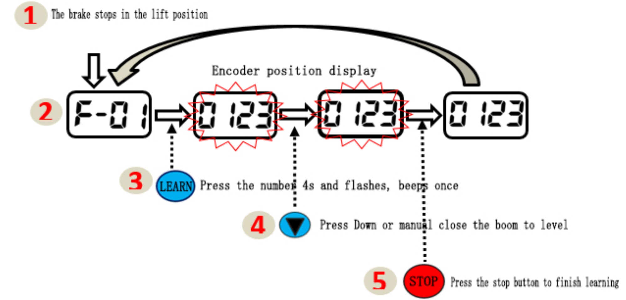
Gate Position Learning
Encoder rotation angle range0-250(3500-1000)(Remark:The AB phase encoder mode can only learn the position after finding the origin.)
Parameter Setting(P-XX Function List)
| No. | Content | Range | Unit |
| P-00 | UP First frequency | 10–100 | HZ |
| P-01 | DOWN Firstly Frequency | 10–100 | HZ |
| P-02 | UP deceleration angle | 0.5-100 | ° |
| P-03 | DOWN deceleration angle | 0.5-100 | ° |
| P-04 | UP Acceleration | 0.03-2 | s |
| P-05 | Down Acceleration | 0.03-2 | s |
| P-06 | UP Deceleration | 0.03-2 | s |
| P-07 | Down Deceleration | 0.03-2 | s |
| P-08 | Up First Strength | 0-150 | % |
| P-09 | Down First strength | 0-150 | % |
| P-10 | Up Second Strength | 0-150 | % |
| P-11 | Down Second Strength | 0-150 | % |
| P-12 | Up Stop Frequency | 1-100 | HZ |
| P-13 | Down Stop Frequency | 1-100 | HZ |
| P-14 | Traffic Light Status Output | 0-1 | 0=ON 1=OFF |
| P-15 | Return To Origin | 0-1 | 0=strong 1=small |
| P-16 | UP Keeping Frequency | 1-100 | HZ |
| P-17 | Down Keeping Frequency |
1-100 | HZ |
| P-18 | Up Keeping Force | 30-150 | % |
| P-19 | Down Keeping Force | 30-150 | % |
| P-20 | UP Time limit | 0.5-20 | s |
| P-21 | Down Time limit | 0.5-20 | s |
| P-22 | Down time without loop detector |
0.1-999 | s |
| P-23 | Resistance rebound power | 50-500 | W(do not change) |
| P-24 | Power limit | 50-500 | W(do not change) |
| P-25 | Auto-Down Delay | 0.1-99 | s |
| P-26 | Aging Test Interva | 0.1-999 | s |
| P-27 | —- | ||
| P-28 | —- | ||
| P-29 | —- | ||
| P-30 | Resistance rebound sensitivity | 0-300 | X 10ms |
| P-31 | —- | ||
| P-32 | Remote Function | 0-1 | 0 OFF 1 ON |
| P-33 | Relay Status Output | 0-1 | 0 OFF 1 ON |
| P-34 | Buzzer | 0-1 | 0 OFF 1 ON |
| P-35 | Down without loop | 0-1 | 0 OFF 1 ON |
| P-36 | Encoder ON | 0-1 | 0 OFF 1 ON |
| P-37 | 3 button Remote | 0-1 | 0 OFF 1 ON |
| P-38 | Deceleration buffer curve | 0-1 | |
| P-39 | Alternate function | 0-1 | 0 OFF 1 ON |
Remark
| P-14 | Green&Red Traffic Light Output Setting As 0 Output as 3 status(UP-Limit,Down-Limit,Middle),Setting as 1is two status. |
| P-15 | Return to origin strength Setting As 0 ,auto-search origin with strong power after power on, Setting As 1 ,auto-search origin with small power after power on(above version 616 has this function) |
| P-33 | Relay Status Output Setting AS 0, After up or down to position, the relay keeping output,setting as 1,relay off after output 1s |
| P-34 | Buzzer: Setting as 0,buzzer not work,setting as 1, up or down buzzer will alarm 0.5s |
| P-35 | Down without loop: Setting As 0,Disable,Setting as 1,arm up and reach to P-22 setting time will down arm automatically. |
| P-36 | Encoder Open: Setting As 0,Sensor limit mode,Setting As 1,encoder limit mode. |
| P-38 | Deceleration buffer curve;setting as 0,Parabolic deceleration ,Setting As 1,S Curve deceleration. |
Note:Set according to the parameter range. Please do not modify it at will; otherwise it will cause the system to work abnormally and dangerously.
System Parameter Setting Step
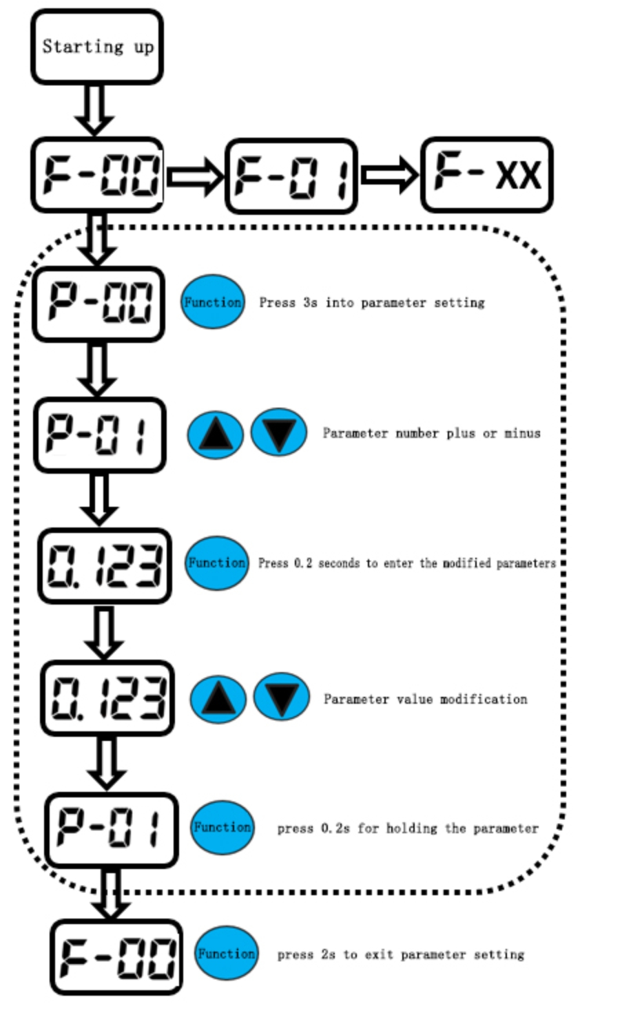
Monitor parameter Function List(F-XX Function List)

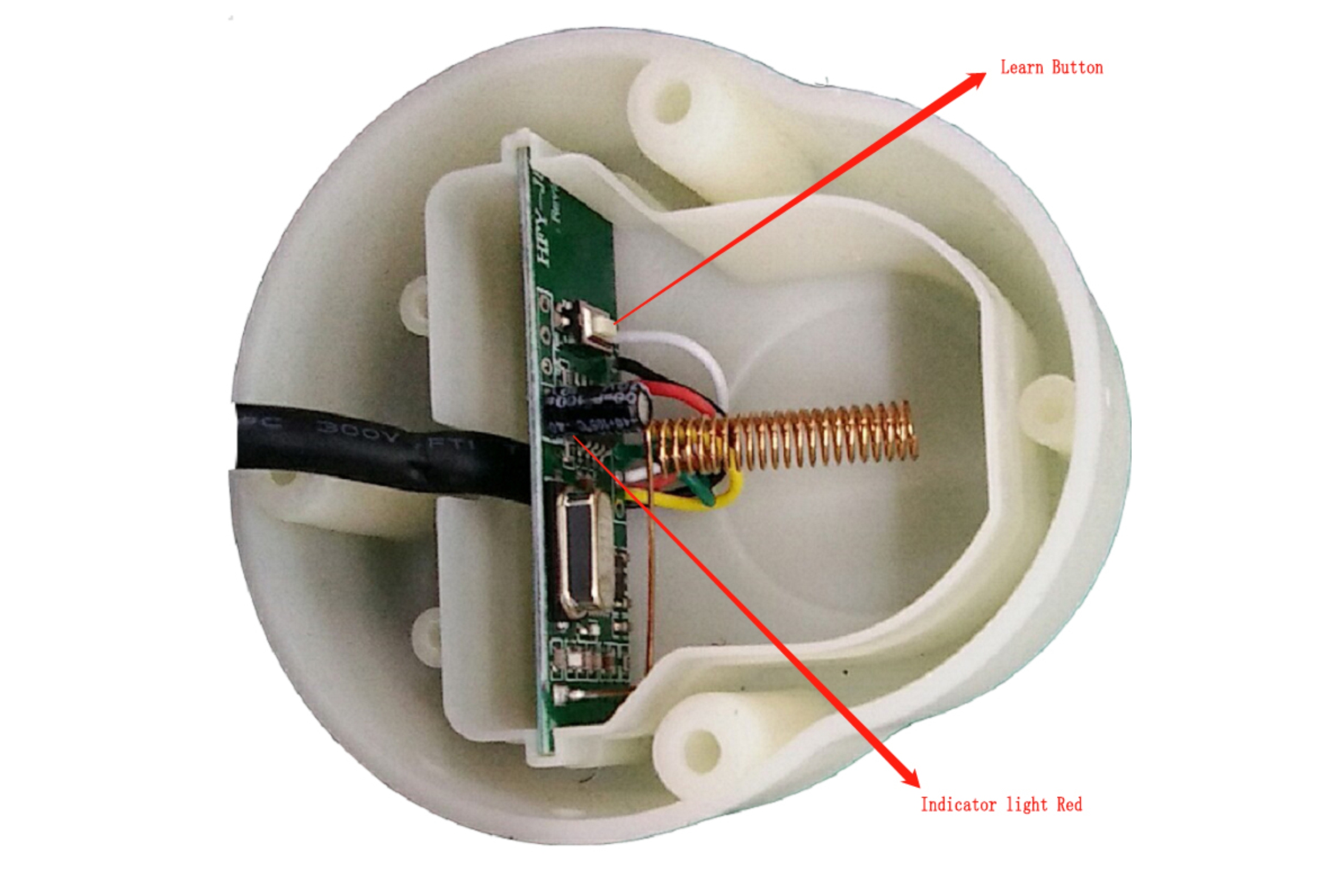
Remote control code description: Disassemble the remote control receiving box, as shown below, 1. Clear the code (clear the original remote control match). Operation method: long press the learning button (the indicator light will be on) until the indicator light is off. Clearing code is complete. 2. Learning (Re-matching the remote control): Press the learning button, the indicator light is on, then press any button on the remote control, the receiving module indicator flashes, and after the flashing stops, the learning is completed.
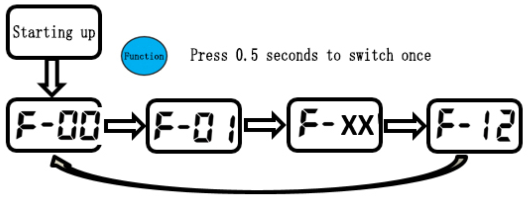
Switch Display Monitoring Parameter Steps
Press ”Function” 0.5s,Switching”Add one”as following photo showing, you can observe the status of the controller running parameters, switch to the number P-12 and press “Function” to return to the number 0, and then cycle.
Automatic Testing Mode
The automatic test function can only be completed in F-XX mode. In F mode, press and hold the up and down until the stop light flashes and then release (usually 5 seconds). The automatic test UP/DOWN time can be modified in parameter P-26. (1-99 seconds), release the automatic test mode Press the stop button in F mode.


Connection Details
| Air Switch connect to AC220V,barrier must connect to GND |
| UP Signal connect to COM and Open |
| Down Signal connect to COM and Close |
| Loop Signal connect to COM Port and Loop function |
6.Trouble shoots
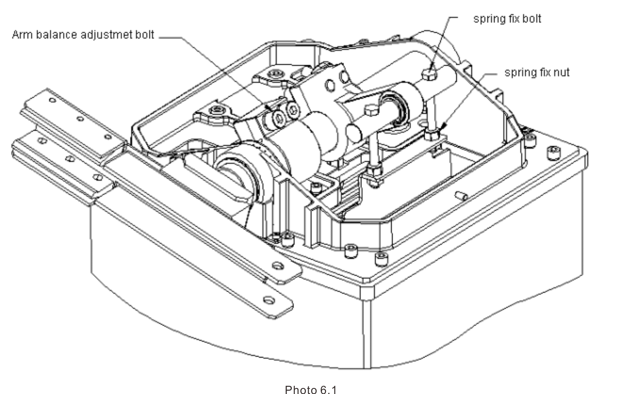
| Fault 1 | boom is in place, but not level. |
| Reason | The mounting base is not horizontal |
| Solution | As shown in Figure 6.1 , open the cover and loosen the drop bar non-leveling screw with Allen wrench ( M12 ) . After adjustingto the ideal level , tighten the screw. |
7.Maintenance
| Once every three months |
| Check the fastening , loose should be tightened |
| v All rotating parts into the oil |
| Once every six months |
| v Check the rotating parts of the wear and tear, serious wear and tear parts should be promptly repaired or replaced |