1.Description
Intelligent barrier adopts the latest international technology ,operation of automation and intelligent function can become realize; meantime add the original clutch device to make sure the barrier with more stable and high reliable status ,also more safe and convenient.
2.Products Parameter
1.Low speed& straight arm barrier:
barrier boom length L<=6M
up(or down)time 6s
Centre high H= 0.83M(the height between barrier boom center to ground)
2.Normal speed& straight arm barrier:
barrier boom length L<=4.5M
Up(or down)time 3s
Centre high H=0.83M(The height between barrier boom center to ground )
3.90 degree folding arm barrier:
barrier boom length L<=5M
up(or down) time 6s
Centre high H=0.83M(the height between barrier boom center to ground)
4.180 degree folding arm:
barrier boom length L<=5M
up(down)time 6s
Centre height H=0.83M(the height between barrier boom center to ground)
5.high speed& strait barrier:
barrier boom length L<=3M
up(down)time 1s
Centre high H=0.83M(The height between barrier boom center to ground)
6.Fence barrier:
barrier boom length L<=4.5M
UP(down)time 6s
Fence height H=0.9M
7.Fence barrier:
barrier boom length L<=4M
Up(down )time 6s
Fence height H=1.5M
3.Function Parameter
1.The clutch on pendulum axis, barrier boom upped quickly by hand under Power status, rest automatically when power off.
2.One motor construction which can apply multiple spring(compressed spring or tension spring),select compressed spring can avoid accident caused by spring breakage.
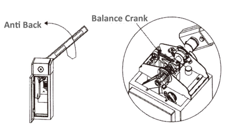
3.Three buttons control “up ””down ””stop” separately.With anti-back function
4. Infrared radiation function(selected)
5.Detector built-in/out function supported.
6.Supporting in-build vehicle loop detector and out-build vehicle loop detector
7.Open/Stop/Close controlling interface
8.RS485 interface(Optional)
9.green/red led indicator interface
10.cable controlling/long range remote controller can be selected
11.when the outside temp is less than zero degree, the system temp can up automatically.
4.Work Environment
◊ Motor work temperature -25-+85
◊ Electronic work temperature -20-+75
◊ Power supply:220V±10% 50/60Hz 110V±10% 50/60Hz
◊ Rated power :120V
◊ Relative humidity:<=90%
◊ Relative distance:>=30M
◊ 7 .Net weight:60kg
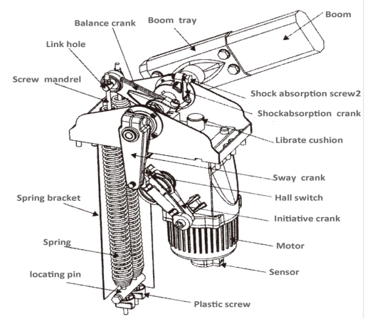
5.Barrier Motor
Extension spring layout
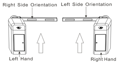
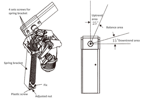
6.Barrier Direction
In order to make right purchase, please refer to the following direction about barrier installation.
7.Installation, Debugging & Use
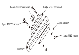
Mechanical part Installation
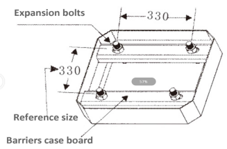
1.Select the right specification barrier according to specific environment .and refer to the following way to fix the anchoring on surface
2.Clockwise rotates handle clutch to “left” position and let the barrier boom in vertical or horizontal position, connect to the power supply ,enter into engine driven condition after everything prepare well.
Mechanical part use
1.Barrier has debugged well before selling, customers can also do further debugging if need be.
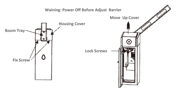
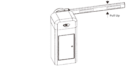
2.Move the case
2.1 Release the screws
2.2 Open gate, release the screws as above photo
2.3 Move the out case
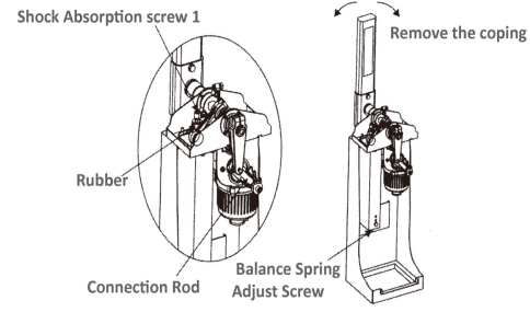
3.Refer to photo 7,when the barrier boom move to vertical position:
barrier boom not in vertical position
A.Screw off “nut 1”to adjust rubber pressure ,if barrier boom still not in vertical position when the rubber no-contract the screw
B.Release screws until barrier boom in vertical position, locking the nut of connecting rod, adjusting shock absorption screws 1 to press the rubber.
C.Refer to photo7-2 to rotate the spring in clockwise direction to add spring tension (tension can not be too heavy)
4.Barrier boom Balance
4.1、Power off and barrier boom up to vertical position by hand as photo7-2 or barrier boom back when come across obstacle as photo8 shows.
A.Open clutch and let barrier boom in vertical position, if the spring tension is too small and the barrier boom can not keep in vertical position, can up the barrier boom to vertical position ,refer to photo7-2, adjust screws by rotating spring at right position to add spring tension.
B、Adjust barrier boom to the position as photo 8 shows, adjusting be finished if barrier boom not move downward.
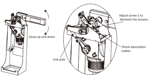
4.2、Transient vibration heavy when come across resistance with barrier boom down procession
A.Power off and let clutch to left position, let the barrier boom to vertical position ,adjust spring at left position to adjust screws for reducing spring tension
B.Repeat operation same as 4.1
C.If the spring tension is too small and can not solve the problems, can refer to photo9, move the spring from link hole 1 to link hole 2, if still not suitable , and need to change spring with smaller diameter and repeat above operation again.
5.When barrier boom move to balance position refer to photo10-1
5.1、barrier boom not balance enough
A.Refer to photo10-2, Release nut 2 for adjusting the pressure of shock absorption screws 2 to rubber, if not in horizontal follow next step please;
B.Refer to photo10-2, release two screws of connecting rod ,rotating connecting rod until barrier boom to horizontal position and then lock screws again.
5.2、 when barrier boon in horizontal position with heavy shake see as photo 10-1:
A.Refer to photo10-2 to adjust shock absorption screws for reduce pressure to rubber ,if not ideal ,follow the next step please.
B.open cultch adjust barrier pole to the vertical position see as photo7-2,rotating balance spring to add or reduce the spring pressure.
C.lock clutch and motor work, if still shake ,repeat the above operation again until the best condition
6.Cultch can not open
For the barrier boom balance not good or shock absorption screws with high pressure to rubber , we need to open clutch ,we can select rotate the clutch by one hand meantime press barrier boom or pull up it.
Spring selection, installation & adjusting
A Spring selection
Balance spring
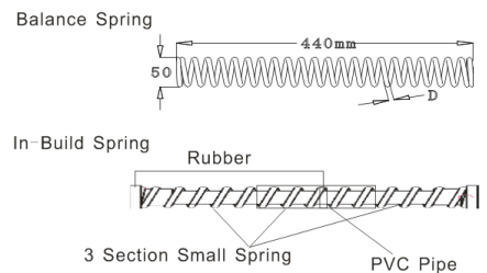
Barrier boom with 5M-6M add the in-build spring specification .in order to make safe or high reliable use, reduce spring fatigue ,we add 3 section small pressure spring extra in traditional pressure spring ,isolate by rubber among springs, three tension spring fixed by PVC tube. Make the in-build spring and installed in balance spring with 6.5mm diameter .
Balance spring form
| NO. | BOOM Length (M) | Spring diameter |
| 1 | 2.5<L<3.5 | D=4.5 |
| 2 | 3.5<=L<=4.0 | D=5.5 |
| 3 | 4.0<L<5.5 | D=6.5 |
| 4 | 5.5<=L<=6.0 | D=6.5 |
B.Spring Installation:
1、put spring into the sleeve;
2、put spring and sleeve into spring bracket together;
3、plug screw rod into spring of sleeve, and fix on the relative link hole;
4、Install baffle ring and screws at the end of screw rod, rotate screw to adjust spring pressure to balance the weight of pole.
C.Spring exchange
- Barrier boom move to the vertical position, if power off we can open the clutch ,push boom to vertical position by hand
- Rotating screws reversed and remove screw and baffle ring.
- Move boon to horizontal position ,remove spring, pull out screw rod
- Release fixing screws of brack, take out spring sleeve and exchange new spring, put into spring bracket. See as (photo11)
- Plug in screw rod and fix it at link hole position
- Let barrier boom at vertical position
- Baffle ring and screws at bottom of screws rod, rotating screw to adding spring pressure to balance barrier boom weight
D .Spring Adjusting
- Rotating screws of screw rod to adjust spring pressure and let it can balance the weight of barrier boom see as photo12
A.Boom can move to vertical position under spring tension force
B.Boon at each position can also keep in balance
C.Within the horizontal position scope, gravity force for move to horizontal position.
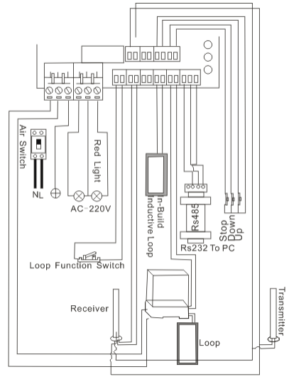
7.Electrical park installation &connection see as photo13
1.220V(110V) power interface:
take off 220v power supply and plug in the power wire
2.The traffic light (R&G light)connection
R&G light connector is 220V power, Connect the red light wire to R output interface ,the green light wire to G output interface, and the COM interface is the loop input interface for the traffic circuit.
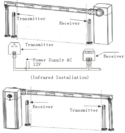
3.Infrared connector
Connect the power supply of infrared transmitter and receiver to relative power output interface, connect to the signal output of receiver to infrared signal terminal of electronic broad see as photo14
4.Inductive loop interface
Support both internal or external loop detector connections (can only select one type).if select external type, only connect to 220V power supply and output signal line connect to loop signal output of the circuit broad .if select internal type ,plug-in loop socket meantime connect the inductive loop to loop signal output terminal.
5.“COM””UP””DOWN” signal input interface
The input interface can work as a switch.Any one of these command short circuit to “COM” port lead to controller response relative action .this port can connect to IC card system meantime also can as wire control interface(wire control interface be recommend for security guarding office )
6.UP/Down limit signal output
It output signal by optocoupler (electronic current refer to circuit broad signal ),selection for user.
7.RS485 Interface
Support UP/DOWN controlled by PC, Plug communication mold on circuit broad ,after connecting three signal lines, plug transfer connector to RS 232 interface of PC .software part operation please refer to detail specification (selectable function )
8.Automatically release interface
Only barrier boom in down limit position, short circuit it can act boom up
Photo13
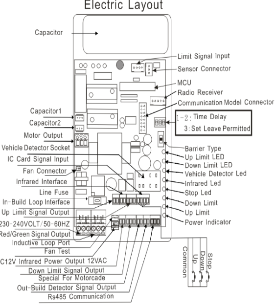
Photo14
Electronic part adjust and notice
- Three buttons to control up/down function: When barrier boom in horizontal position, press ”up” button and barrier boom rise; when barrier in vertical position ,press “down” and barrier boom fall; within falling and rising procession, press “stop” barrier boom stop moving.(when barrier within falling and rising procession, press “down” and barrier without any response)
- anti-back function: when barrier come across resistance within falling and turn to raising status automatically.
- Infrared function: if infrared signal be cut off within falling process and turn to raising condition automatically.
- Green/red traffic light interface, barrier boom in vertical position and green light on ;inversely barrier in falling or horizontal position and red light on;
- Inductive loop function: if inductive loop installed well, if there has vehicle on loop within falling procession and turn to rising situation automatically. if vehicle still on loops, press “down” will not be any reaction until vehicle left and buzzer alarm, barrier boon falling automatically.
- Temperature rising automatically: if work temperature lower than 5 degree, motor temperature will raising controlled by controller .the buzzer will emit “da da” sound each 2s within temperature raising .
If other abnormal condition happens please contract our technician!
8.Common failures and processing method
1.Motor work but barrier boom without any response
A. Check the clutch locked or not
2.check rubber damage or not, if damage please change new one
B.Check spring fatigue deformation or not,if deformation please adjust screws or change new spring
3.Boom can not down or up to the right position
A.Without adjusting spring when length boon to change shorter one, please adjust according to specification.
B.Sensor can not plug in well
C.wrong barrier type
4.remote distance shorter than before
A.Power not enough, please change battery
5.press remote controller ,barrier boom without and response
A.Check power supply
B.Check FUSE damage or not
C.Make sure the code of remote controller same with the main controller or not
6.There is no reaction on motor but indicator work normal when user changes the control broad
A.Please check the capacitance is correctly or fixed or not.
B.Please check the sensor is right insert or not.
7.if user change a new control broad and the boom is abnormal when rising and falling
A.Please adjust the GATE type selection (refer to control broad)
9.Packing list
| Name | Spec | Quant | Unit | Remark |
| hex screw | M12x700 | 2 | Pcs | fix boom |
| Boon plate | 1 | Pcs | ||
| Case plate | 2 | Pcs | Fix barrier body | |
| Expansion bolt | M12x150 | 4 | Set | Fix barrier body |
| Clutch key | 2 | Pcs | ||
| Case key | 2 | Pcs | ||
| Desk remote controller | 1 | Pcs | ||
| Remote controller | 2 | Pcs | ||
| User manual | 1 | Set |
Attachment
1 .Remote code
If the remote controller or remote type infrared device not equipped with our controller, need to change the remote code same as the controller,please refer to following procession
Remote Identification code:on the back surface of remote controller or the transformer of controller attache remote code, user can coding according this code.
Hand shake code:open cover and take out battery,we can see the code from right to left on PCB with last code as the first bit,middle pad short circuit last as “1”,empty as “X”(same as remote type infrared code)
The following code as 01XX1X0X
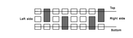
Attention:before coding by searing iron, must take out battery.
Infrared device installation show as photo15
10.Service Item
1.Motor& control broad offer 1 year maintain for free
2.Offer paid service within barrier whole life
3.Technology support
The following circumstance without service scope
A.Wrong installation not according to user manual
B.Power supply not stable and exceed specified power supply scope ,not according to national security standards
C.Bad installation lead to appearance damage
D.Force majeure like Natural calamities lead to damage
E.Exceed guarantee time
F.Not equipped service
Products upgrade we not inform again
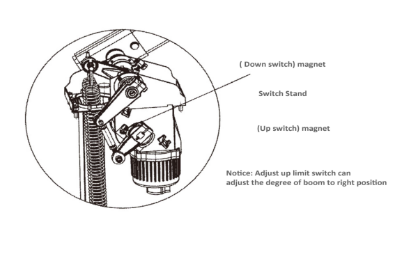
Limit switch adjust
1.The blue color near to main axis as up limit shade;
When pole at horizontal position, adjust shade and let it no more than 90 degree with the boom. the green led indicator on when the shade in slot. adjusting shade by watching the degree between vertical position and horizontal position for boom be in the best vertical degree.
2.The blue color near to boom of main axis as the down lime shade;
When pole at vertical position ,adjust shade and let it no more than 90 degree with boom .the red led indicator on when the shade in slot, system act as down limit, barrier in down limit condition .view the boom horizontal degree to adjust shade to make sure boom in best vertical degree.